7
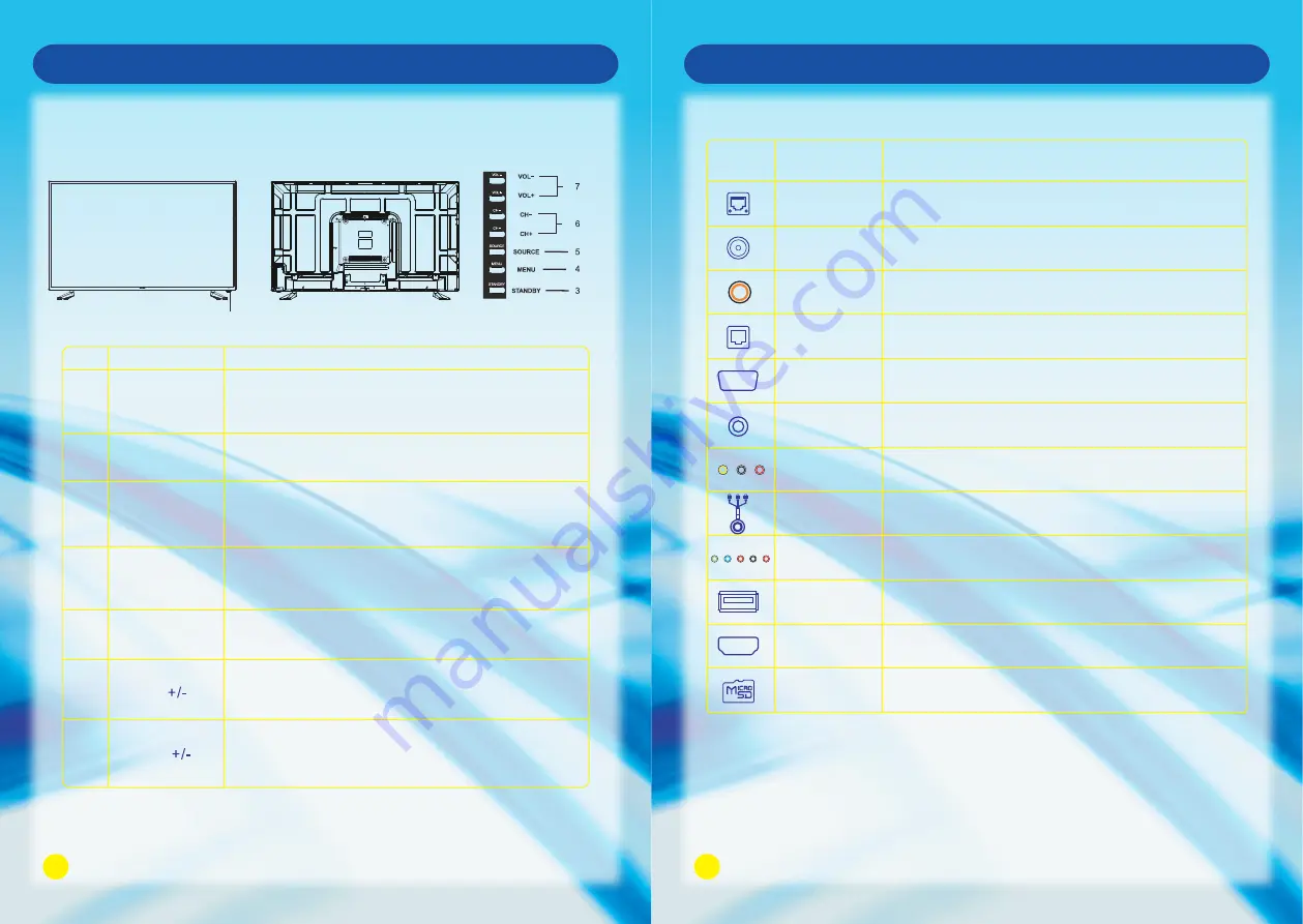
Front Panel
No.
1
2
3
4
5
6
7
Name
Remote Control
Sensor Window
Power Indicator
Description
Receives the signal from the Remote Control. Do not
put any objects in front of the window in order not to
hinder the reception of signal.
Flashes red when the unit is powered on:
Lights up red when the unit is in standby mode.
Press to display all possible input signal sources.
Press to cycle through various sources.
SOURCE
Press this button to display the OSD menu.
When the OSD menu is on, press this button to exit the
menu.
MENU
Press this button to turn the unit on when it is in standby
mode.
Press this button once more to put it to standby mode.
STANDBY
Press VOL + to increase volume, or VOL - to decrease.
At the OSD menu, press these buttons to move the
selection focus left and right to change settings.
VOL
Press these buttons to sequentially select channels.
When the OSD menu is on, press these buttons to
move the selection focus up or down to change settings.
CH
Main Unit Control
8
Connection and Setup
Terminals on TV
Digital Audio Out
(O
PTICAL
)
Connect to Digital Audio Amplifier O
PTICAL
Input.
Icon
HDMI
ETHERNET
Connect the RJ45 Interface Ethernet.
Name
Description
Connect to HDMI signal.
AV OUT
Connect to PVR or RECOREDR.
VGA Audio In
Connect the DVI or VGA Audio Signal.
VGA
Connect the PC VGA Signal.
ANT IN
Connect to External Antenna.
USB
Connect for media files playback and program recording.
(USB3.0 is not compatible with USB 1.1)
Note: Above is the universal version of all SONIQ Smart TV. Some terminals may not be
contained for some products, for that please obey the entity display.
Digital Audio Out
(COAXIAL)
Connect to Digital Audio Amplifier COAXIAL Input.
COMPONENT IN
Connect the Component Video
and Audio
Signal.
AV IN
Connect Composite Video and Audio Signal.
Micro SD
SD card reader slot.
Front View
Back View


