


LKZ-1500-
LITE ● LKZ-1500 – USER MANUAL
42
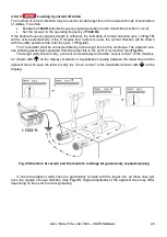
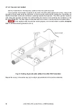
Connect one lead of the Transmitter to a damaged conductor (See
); the opposite end
shall be protected. The second lead of the Transmitter shall be grounded with a pin placed at the dis-
tance of no less than 5 m. from the cable. Preset the double frequency
φ
. Select the
Trace
mode and
frequency of the
φ 8928
on the Receiver. Stand directly over the utility line at the beginning of the
tested plot. Make sure that you are not closer than 20 m to the point of connection of the Transmitter.
Press the
button on the Receiver to reset the phase indications. Move along the target line,
directly over it, and control the position with the null scale; take phase readings carefully. The phase
may change smoothly.
The phase change rate will rise by several magnitudes with the polarity
sign changing over where the insulation fault is located or directly downstream of it
. When the
insulation fault is passed by, the phase readings will smoothly vary at a low rate.
The flaws of this method are as follows:
phase fluctuation within the areas of damaged insulation is less obvious than signal fluctuation
by the insulation control sensor tracing method for example A-frame,
interferences from adjacent utilities.
6
Data storage, GPS navigation
The Receiver stores the measured data in the non-volatile memory, including position from exter-
nal GPS module. Connection to the external GPS module is wireless.
The following parameters may be stored in the Receiver memory both with GPS coordinates and
without them:
strength of signals from magnetic antennas and at the SENSOR input (see sec. 4.6.2);
direction to utility line (see sec. 4.6.2.1);
depth of utility and current flowing through it (see sec. 4.6.3);
direction of tracing current (see sec. 4.6.2.5);
relative polarity at the “SENSOR” input (see sec. 5.2);
signal phase at the “Trace” input (see sec. 5.2.3.3);
operating frequencies,
local time and date at the moment of readings through GPS,
target point coordinates obtained through the GPS.
Precise co-ordinate position depends on such factors as quantity of satellites within the direct vis-
ibility, satellite arrangement, reflected signals, if any, influence of ionosphere, satellites chronometer
errors and technical characteristics of the GPS module.
With dedicated GPS transmitters,
the accuracy can be improved to 1 cm
.
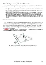
The manufacturer warrants proper performance of the LKO Transmitter if interfaced with
these GPS module types: GT-750, Holux M1000, or RCV3000.
If a wired GPS receiver is used which provides a high accuracy of readings, it is essen-
tial for the device to output data compliant with the NMEA-0183 RMC and GGA formats
and a 1 Hz refresh rate.
Summary of Contents for LKZ-1500
Page 1: ......
Page 2: ......
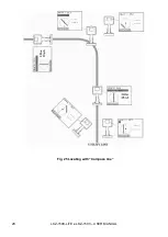
Page 18: ...LKZ 1500 LITE LKZ 1500 USER MANUAL 16 Fig 10 LKO 1500 receiver panel...
Page 30: ...LKZ 1500 LITE LKZ 1500 USER MANUAL 28 Fig 25 Locating with Compass line...
Page 57: ...LKZ 1500 LITE LKZ 1500 USER MANUAL 55 NOTES...
Page 58: ...LKZ 1500 LITE LKZ 1500 USER MANUAL 56 NOTES...
Page 59: ......
Page 60: ......