background image


Lodestar Hardware 

Manual


Document Ref: UM-8084-101 

Issue: A– Rev 8 

© Sonardyne International Limited 2013


57 

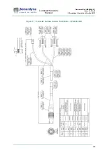
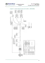
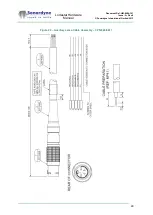
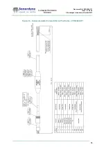
Figure 29 – Subsea Lodestar Transceiver Test Cable – CPN 820-0078 


Summary of Contents for Lodestar

Page 1: ...Sonardyne International Limited 2013 1 UM 8084 101 Lodestar Hardware Manual Head Office Sonardyne International Limited Blackbushe Business Park Yateley Hampshire GU46 6GD United Kingdom T 44 0 1252 872288 F 44 0 1252 876100 E support sonardyne com www sonardyne com ...

Page 2: ...structions Updates for PC Utility release Updated formatting Updating cable drawings for new versions Deletion of cable drawings All 6 1 6 2 All All All 7 1 All All Appendix A Appendix A All All All All All 41 All All 44 48 50 59 49 60 Copyright 2013 Sonardyne International Limited Blackbushe Business Park Yateley Hampshire GU46 6GD United Kingdom Tel 44 0 1252 872288 Fax 44 0 1252 876100 All righ...

Page 3: ...erformance 23 5 Installation 25 5 1 Introduction 25 5 2 Unpacking and inspection 25 5 3 Installation location 26 5 4 Site preparation 27 5 5 Alignment 29 5 6 Connections 29 5 7 NMEA Connections to Listening Equipment 30 6 Troubleshooting 31 6 1 Introduction 31 6 2 Test Procedure 31 6 3 Check List 33 6 4 General information and action to take 33 6 5 Recovery Procedures 34 6 5 1 Lodestar Reset 34 6 ...

Page 4: ...ce Locations 41 Figure 15 Lodestar Surface Console Cable Tail CPN 820 0054 43 Figure 16 Lodestar Surface Console Test Cable CPN 820 0057 44 Figure 17 Lodestar Surface Comms Test Cable CPN 820 0061 45 Figure 18 Lodestar Surface Transceiver Cable Tail CPN 820 0062 46 Figure 19 Lodestar Surface Transceiver Test Cable CPN 820 0064 47 Figure 20 Auxiliary Lemo Cable Assembly CPN 820 6817 48 Figure 21 Gy...

Page 5: ... Hardware Manual Document Ref UM 8084 101 Issue A Rev 8 Sonardyne International Limited 2013 5 Tables Table 2 Battery and charge status LEDs 11 Table 3 Transceiver and data LEDs 12 Table 5 Lodestar Versions 17 ...

Page 6: ...to the referenced location If required the reader can print any part of this Hardware Manual However the reader cannot select copy or change any part of it Copyright in this manual remains with Sonardyne International Limited at all times Please refer to the on line help for your PDF Reader software to understand how to use all the features available for searching and navigating the manuals 2 2 Ho...

Page 7: ...technical and user information to help deliver the best performance from the Lodestar Anyone who uses the Lodestar should make sure they read the relevant parts of this manual If the computer that holds this electronic manual is connected to a printer any part of it can be printed Operation manuals Operation manuals are supplied separately describing how to configure and use the Lodestar for speci...

Page 8: ...yne s experience with underwater acoustic navigation systems has been applied to overcome the problems associated with conventional sensor platforms such as temperature shock Lodestar provides the following as standard industry standard output telegrams battery backup to maintain uninterrupted operation in the event of brief power failure Battery operation will last up to two hours when using a ba...

Page 9: ...the Lodestar AHRS to be as simple as possible to install connect configure and operate To support this design principle the front panel of the Surface Lodestar has only a single operator control a series of LED status indicators and eight ports to connect Lodestar with external equipment and supplies The Surface Lodestar is shown in Figure 1 Figure 1 Surface Lodestar Front Panel Table 1 lists and ...

Page 10: ...llows direct serial connection between Lodestar and Sonardyne acoustic transceivers or other external instruments These ports are also both available to transmit measurements from Lodestar to receiving equipment receive aiding information from external sources for example a GPS receiver send or receive a trigger signal 8084 135 46 47 Power In A 3 way male inlet port that accepts electrical power f...

Page 11: ... maintain the Lodestar operation for up to three hours from a fully charged condition An LED on the front panel indicates when the Lodestar is operating on the internal battery Indicator LEDs Five LEDs indicate the status of power and communications for the surface Lodestar BATTERY AND CHARGE STATUS LEDS There are two LEDs to show the status of Battery Charge and of the External Supply Table 2 exp...

Page 12: ...d grounding point on the vessel This connection is in addition to the ground connection made through the cable CAUTION The Surface Lodestar must be permanently bonded to a suitable grounding point on the vessel using the grounding stud 16 AWG cable or better should be used for this 3 3 Connectors of the Subsea Lodestar The subsea version of the Lodestar AHRS does not include any operator controls ...

Page 13: ...on between Lodestar and external equipment This port can transmit measurements from Lodestar to receiving equipment receive aiding information from external sources for example a GPS receiver send or receive a trigger signal 8084 138 54 55 T1 Port T2 Port Two 6 way female ports allow direct serial connections between the Lodestar and Sonardyne acoustic transceivers or other external instruments Th...

Page 14: ... a built in self test routine While operating in this mode the Lodestar sends information about itself and its configuration through the Console port to a receiving PC for example Firmware Loader Version 1 03 01 25 Feb 17 2010 09 23 33 CPU UART FPGA 3 CPU Interconnection FPGA 2 SDHC Card capacity 7948206080 bytes Loading firmware Note The communication parameters used for the Console port are init...

Page 15: ...m the date of shipment from Sonardyne International Limited unless otherwise stated This warranty is limited to the replacement or at Sonardyne s option repair free of cost F O B Sonardyne s loading bay in Yateley UK provided the equipment was not abused or operated other than in accordance with the instructions in this User Manual All warranty repair claims must be returned to Sonardyne with a le...

Page 16: ... and but for this allocation and limitation of liability Sonardyne would not have agreed to supply the products Copyright and Disclaimer Sonardyne International Limited asserts its ownership of the copyright in this User Manual All product names referenced in this document are trademarks of their respective companies Use of a term in this document should not be regarded as affecting the validity o...

Page 17: ...specifications included in this chapter are subject to change without notice If necessary contact Sonardyne International Limited for details of the current specification Product Versions Table 5 lists the versions of the Lodestar currently available Table 5 Lodestar Versions Part Number Description 8084 000 0000 IP67 rated surface version 8084 000 1110 1000 m depth rated version 8084 000 3110 300...

Page 18: ... Ref UM 8084 101 Issue A Rev 8 Sonardyne International Limited 2013 18 4 2 Physical Surface version The physical specification of the Surface Lodestar are shown in Figure 3 and Figure 4 Figure 3 Physical specifications Surface Lodestar ...

Page 19: ...Lodestar Hardware Manual Document Ref UM 8084 101 Issue A Rev 8 Sonardyne International Limited 2013 19 Figure 4 Physical specifications Surface Lodestar continued ...

Page 20: ...ef UM 8084 101 Issue A Rev 8 Sonardyne International Limited 2013 20 Subsea versions The physical specifications of the Subsea Lodestars are shown in Figure 5 Figure 6 and Figure 7 Figure 5 Physical specifications 1000 m Subsea Lodestar ...

Page 21: ...Lodestar Hardware Manual Document Ref UM 8084 101 Issue A Rev 8 Sonardyne International Limited 2013 21 Figure 6 Physical specifications 3000 m Subsea Lodestar ...

Page 22: ...Lodestar Hardware Manual Document Ref UM 8084 101 Issue A Rev 8 Sonardyne International Limited 2013 22 Figure 7 Physical specifications 5000 m Subsea Lodestar ...

Page 23: ...nterface Number of digital ports 4 Protocol RS232 OR RS485 Ethernet Single 100BaseT Ethernet port Analogue Output Range 10 V Resolution 12 bit Minimum load 10 kΩ 30 nF 4 4 Environmental Mechanical Surface Aluminium casing powder coated Subsea Anodised aluminium 1000 3000 m Super Duplex Stainless Steel 5000 m Ingress Surface IP66 Subsea 1000 3000 or 5000 metres depth rated Operating temperature 10 ...

Page 24: ... Roll and Pitch Range 90 no physical limit Accuracy 0 01 Resolution 0 01 Heave Range 99 metres Accuracy real time The greater of 5 cm or 5 of measured heave Bandwidth User selectable Resolution 0 01 metres Note The power demand listed above is correct for the Lodestar when used as a standalone instrument ...

Page 25: ...e vessel It explains all the electrical and data connections required and provides information to help use Lodestar with multiple data receiving units 5 2 Unpacking and inspection Handling The Lodestar AHRS includes a number of delicate and sensitive electronic components In particular the accelerometers and Ring Laser Gyroscopes RLGs that form the Inertial Measurement Unit IMU are sensitive to sh...

Page 26: ...ocation must not exceed the environmental limits for temperature defined in section 4 4 on page 23 Do not subject Lodestar to regular and rapid changes in temperature The location must provide a mounting surface that is level with respect to the vessel s body frame and of sufficient strength to support the Lodestar s weight safely and without flexing The location must provide access for power and ...

Page 27: ...a version of the Lodestar The surface version uses three M8 stainless steel socket cap head bolts and washers to secure the Lodestar to the mounting location Sonardyne does not supply these fixing bolts You can use a similar mounting plate to secure the subsea version of the Lodestar or you can use strong stainless steel straps and protective rubber strips to secure the Lodestar to a convenient lo...

Page 28: ...Lodestar Hardware Manual Document Ref UM 8084 101 Issue A Rev 8 Sonardyne International Limited 2013 28 Figure 8 Mounting arrangement Surface Lodestar Figure 9 Mounting arrangements Subsea Lodestar ...

Page 29: ... vessel ROV or platform the mounting angles will need to be measured and configured on the Lodestar The Lodestar can be configured for any mounting angle that may be required An in depth description of the theory and process for measuring and configuring mounting angles can be found in the Lodestar AHRS Operation Manual UM 8084 107 Also within this manual is an explanation for the effects of misal...

Page 30: ...bias and power dissipation at the opto diode as shown above The receive circuit must be designed for operation with a minimum differential input voltage of 2 0 V and must not take more than 2 mA current from the line at that voltage In the arrangement shown in Figure 17 all signal line A connections must be connected to the listener device A connections and signal B connections connected to listen...

Page 31: ...n about the Lodestar configuration in use at the time when the problem occurred You can do this by supplying a copy of the relevant configuration file saved automatically by the Lodestar see Lodestar AHRS Operation Manual UM 8084 107 for instructions Specific Lodestar logged output may be requested 6 2 Test Procedure Figure 11 shows the recommended test procedure to follow if it is suspected that ...

Page 32: ...Lodestar Hardware Manual Document Ref UM 8084 101 Issue A Rev 8 Sonardyne International Limited 2013 32 Figure 11 Lodestar test procedure ...

Page 33: ...ral description of problem The more information supplied about the nature of the problem the easier it will be to provide fast and effective support Events leading up to the problem What actions were taken immediately prior to the problem Provide details about the steps taken before the problem was observed The more details provided the more likely it will be that the fault can be reproduced or to...

Page 34: ... in the terminal window note the use of uppercase letters You may need to enter UNLK and press return several times Restoring Factory Settings 6 5 2 Restore Lodestar Factory Settings Lodestar can be commanded to restore its factory default settings CAUTION If factory settings are restored the all previous user defined settings in Lodestar will be lost It is recommended a careful note is taken of a...

Page 35: ...firm that you want to reset Lodestar to default The PC Utility will reboot Lodestar and reset it to factory default state It will then wait for Lodestar to re boot After the boot process has completed the PC Utility will attempt to connect to Lodestar using factory default settings If successful then information concerning the lodestar will be displayed ...

Page 36: ...rdyne support The process for upgrading firmware is explained below Before upgrading the firmware ensure you have the following available The new firmware file IMU hex A serial connection to the Lodestar on the console port Connect to Lodestar Connect the Lodestar Console port to the PC either directly via RS232 or through an NSH If using a test cable then check that the blue connectors are joined...

Page 37: ...imited 2013 37 Start the Firmware Upgrade Press the Download Firmware button Confirm that you wish to upgrade firmware by pressing Yes The following dialog box will be displayed First select the file to download by browsing to the folder containing the new IMU HEX file supplied by Sonardyne ...

Page 38: ...odestar firmware file Press YES to continue Next select a baud rate for the download Sonardyne recommends 115200 baud for all firmware downloads Finally press Start to commence the download At this point the progress bar will begin to increment and the bytes transferred will increase Download time at 115200 is less than 5 minutes Do not interact with the PC while the download is in progress ...

Page 39: ...l Limited 2013 39 Once the download is complete press the Done button At this point the utility will re boot the Lodestar Once complete the PC Utility will re program Lodestar to give it the same configuration that it had before the upgrade began Therefore it should now be ready for use ...

Page 40: ...e that emergency requests are dealt with immediately during office hours and are responded to within 30 minutes at all other times Please note the helpline is for emergency use only Do not use it for general enquiries General enquiries should be directed to local Sonardyne offices Alternatively use one of the dedicated e mail groups Please note that e mails are answered only during normal office h...

Page 41: ...2 1 1 UK Headquarters Sonardyne International Ltd Blackbushe Business Park Yateley Hampshire GU46 6GD United Kingdom T 44 0 1252 872288 F 44 0 1252 876100 E sales sonardyne com 8 2 1 2 UK Aberdeen Sonardyne International Ltd Units 12 14 The Technology Centre Claymore Drive Bridge of Don Aberdeen AB23 8GD United Kingdom T 44 0 1224 707875 F 44 0 1224 707876 E sales sonardyne com 8 2 1 3 USA Houston...

Page 42: ...Sonardyne Asia Pte Ltd 34 Loyang Crescent Block B Singapore 508993 Tel 65 6542 1911 Fax 65 6542 6937 e mail asia sales sonardyne com 8 2 1 5 Brasil Rio das Ostras Sonardyne Brasil Ltda Av Zen lotes 05 e 06 Quadra D Zen Rio das Ostras RJ CEP 28 890 000 Brasil T 55 22 2123 4950 F 55 22 2123 4951 E brasil sales sonardyne com ...

Page 43: ...Lodestar Hardware Manual Document Ref UM 8084 101 Issue A Rev 8 Sonardyne International Limited 2013 43 Appendix A Cable Drawings Figure 15 Lodestar Surface Console Cable Tail CPN 820 0054 ...

Page 44: ...Lodestar Hardware Manual Document Ref UM 8084 101 Issue A Rev 8 Sonardyne International Limited 2013 44 Figure 16 Lodestar Surface Console Test Cable CPN 820 0057 ...

Page 45: ...Lodestar Hardware Manual Document Ref UM 8084 101 Issue A Rev 8 Sonardyne International Limited 2013 45 Figure 17 Lodestar Surface Comms Test Cable CPN 820 0061 ...

Page 46: ...Lodestar Hardware Manual Document Ref UM 8084 101 Issue A Rev 8 Sonardyne International Limited 2013 46 Figure 18 Lodestar Surface Transceiver Cable Tail CPN 820 0062 ...

Page 47: ...Lodestar Hardware Manual Document Ref UM 8084 101 Issue A Rev 8 Sonardyne International Limited 2013 47 Figure 19 Lodestar Surface Transceiver Test Cable CPN 820 0064 ...

Page 48: ...Lodestar Hardware Manual Document Ref UM 8084 101 Issue A Rev 8 Sonardyne International Limited 2013 48 Figure 20 Auxiliary Lemo Cable Assembly CPN 820 6817 ...

Page 49: ...Lodestar Hardware Manual Document Ref UM 8084 101 Issue A Rev 8 Sonardyne International Limited 2013 49 Figure 21 Gyro Power Cable CPN 820 6828 ...

Page 50: ...Lodestar Hardware Manual Document Ref UM 8084 101 Issue A Rev 8 Sonardyne International Limited 2013 50 Figure 22 Lodestar Subsea Console Cable CPN 820 0065 ...

Page 51: ...Lodestar Hardware Manual Document Ref UM 8084 101 Issue A Rev 8 Sonardyne International Limited 2013 51 Figure 23 Lodestar Subsea Console Test Cable CPN 820 0067 ...

Page 52: ...Lodestar Hardware Manual Document Ref UM 8084 101 Issue A Rev 8 Sonardyne International Limited 2013 52 Figure 24 Subsea Lodestar Comms C1 Cable CPN 820 0068 ...

Page 53: ...Lodestar Hardware Manual Document Ref UM 8084 101 Issue A Rev 8 Sonardyne International Limited 2013 53 Figure 25 Subsea Lodestar Comms C1 Test Cable CPN 820 0070 ...

Page 54: ...Lodestar Hardware Manual Document Ref UM 8084 101 Issue A Rev 8 Sonardyne International Limited 2013 54 Figure 26 Subsea Lodestar Comms Ethernet Tail Cable CPN 820 0071 ...

Page 55: ...Lodestar Hardware Manual Document Ref UM 8084 101 Issue A Rev 8 Sonardyne International Limited 2013 55 Figure 27 Subsea Lodestar Comms Ethernet Cable CPN 820 0072 ...

Page 56: ...Lodestar Hardware Manual Document Ref UM 8084 101 Issue A Rev 8 Sonardyne International Limited 2013 56 Figure 28 Subsea Lodestar Transceiver Cable Tail CPN 820 0073 ...

Page 57: ...Lodestar Hardware Manual Document Ref UM 8084 101 Issue A Rev 8 Sonardyne International Limited 2013 57 Figure 29 Subsea Lodestar Transceiver Test Cable CPN 820 0078 ...

Page 58: ...Lodestar Hardware Manual Document Ref UM 8084 101 Issue A Rev 8 Sonardyne International Limited 2013 58 Appendix B Lodestar Reference Frame Figure 30 Lodestar Reference Frame ...

Reviews: