background image

7

SONARC SOFTWARE

NETWORK CONNECTION

INSTRUCTIONS

Equipment List

Connecting to Your SONARC Homepage

1.  Computer or tablet
2.  Network router with DHCP service enabled
3.  Two RJ-45 cables (one when using wireless) 

1.  The amplifier’s factory settings has DHCP set to ON. 
2.  Connect the amplifier to a network with a router. 
  Make sure the computer and amplifier are on the  
  same network. 
3.  Turn on the amplifier. 
4.  The amplifier will be issued an IP address by the router. 
5.  Use an IP Scanner to determine the IP Addresses of the
  Sonance DSP amps on the network. We recommend 
  Fing app for IOS, Advanced IP Scanner for Windows  
  devices and LanScan for macOS. 
6.  Network devices will show up and the amplifier will be
  named Sonance. 
7.  Open Safari or Chrome. 
8.  In the URL address window at the top, enter the  
  IP address of the Sonance DSP amplifier to configure. 

SONARC Legend

Toggle/
Pull-down Menu

Free Type Field

Single Action Menu

SONARC Homepage

Setup Options

Your SONARC Homepage will have two options for setup; 
Basic Setup and Advanced Setup. Amplifier name can be 
entered by the installer. 
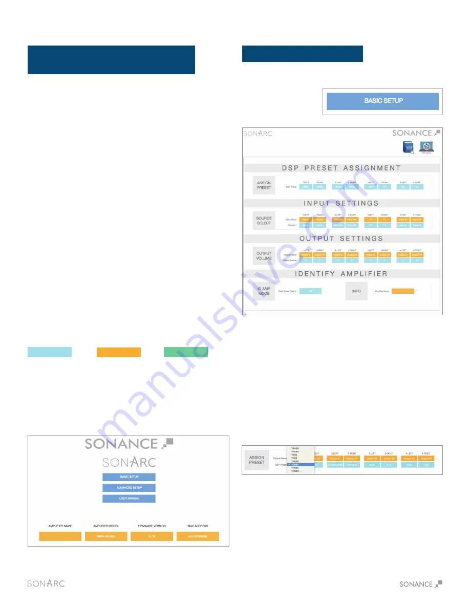
BASIC SETUP PAGE

DSP Preset Assignment

Assign Preset

Basic Setup

This page is for basic set up of EQ, Source and Volume.

Click on the individual channels to show the drop down menu 
of preset options. Once you locate the preset for your Sonance 
speakers click on the name to set the preset. Each Sonance 
DSP amplifier has 50 slots with pre-configured DSP curves for 
Sonance speaker models pre-loaded. If the speaker model in 
your application is not on the pre-loaded list, hundreds of DSP 
files are available for download from the Sonance website. 
Download the preset file for additional Sonance speaker 
models at www.sonance.com/electronics/amplifiers/dsp.

To start, click on the 
Basic Setup button.

Summary of Contents for DSP 8-130 MKII SONAMP

Page 1: ...DSP 8 130 MKII SONAMP MULTI CHANNEL POWER AMPLIFIER WITH INSTRUCTION MANUAL 06 14 17...

Page 2: ...and Volume Level Controls 6 Protection Circuitry and LEDs 6 Rack Ear Installation and Shelf Mounting 6 Software V2 7 Network Connection Instructions 7 Homepage 7 Basic Setup Page 7 Advanced Setup Pag...

Page 3: ...e amplifier use canned air or wipe the amplifier with a soft cloth Do not use solvents as they may damage the amplifier 12 Non use periods Unplug the amplifier s power cord from the outlet when the am...

Page 4: ...e interventions av rera n cessaire si l appareil a t endommag pour quelque raison que ce soit et par exemple si le c ble d alimentation secteur ou sa prise sont endommag s si du liquide a p n tr l int...

Page 5: ...mp DSP 8 130 MKII box should contain 1 Quickstart guide 1 Sonamp DSP 8 130 MKII amplifier 1 IEC power cord 4 Feet 2 Rack ears Unpacking Save the carton and polystyrene inserts for future safe transpor...

Page 6: ...g channels use the two outside connections on each connector The positive wire from the speaker should be on the left side connection and the negative connection should be on the right side Auto On Vo...

Page 7: ...CAUTION RISK OF ELECTRIC SHOCK DO NOT OPEN AVIS RISQUE DE CHOC ELECTRIQUE NE PAS OUVRIR S N T5AL 250VAC 2 100 AC 100 120V 60Hz CAUTION REPLACE FUSE ONLY WITH SAME TYPE AND RATING ATTENTION REMPLACER U...

Page 8: ...r extremely low impedance the affected channel outputs automatically mute The output of the effected channel will remain muted until the fault has been corrected Only the effected channels output will...

Page 9: ...he IP address of the Sonance DSP amplifier to configure SONARC Legend Toggle Pull down Menu Free Type Field Single Action Menu SONARC Homepage Setup Options Your SONARC Homepage will have two options...

Page 10: ...T AND RIGHT CHANNELS ARE LINKED OUTPUT VOLUME IS LINKED TO TURN ON VOLUME IN BASIC SETUP ADVANCED SETUP PAGE GENERAL SETTINGS TAB Advanced Setup IP SETUP DHCP On Off To start click on the Advanced Set...

Page 11: ...ep Mode options Each channel has an independent Sleep Mode setting The Sleep Mode is triggered by an audio sensing circuit on each channel of the amplifier Voltage Green In the Voltage Green Auto On m...

Page 12: ...ments of 5dB This is a user entered field with a maximum of 15 characters Use these fields to describe the location of the speakers Allows each channel to be set for Stereo or Mono operation When Mono...

Page 13: ...RC software includes a built in pink noise generator The pink noise signal can be used in conjunction with a real time analyzer to measure speakers You have the option of pink noise or test signals fe...

Page 14: ...se Import Single Preset Copy Preset 1 Import speaker preset to a location on your computer This can be accomplished by saving a DSP preset downloaded from Sonance website 2 Select the location you wou...

Page 15: ...k of damage to the loudspeakers Crossover LP Xover HP Xover Frequency Filter Type Limiter This setting turns the high and low pass crossovers ON and OFF In this field you can enter any frequency betwe...

Page 16: ...riven 4 ohms sinewave 1 8 power 226 Watts all channels driven idle 35 Watts Sleep Mode 1 1 Watts Voltage or Audio Green 0 45 Watts Power Consumption 220V AC 8 ohms sinewave full power 1097 Watts all c...

Page 17: ...eset Steps Step 1 Turn amplifier off Step 2 With light pressure adjust 1L Volume Control full counter clockwise Step 3 With light pressure adjust 1R Volume Control full clockwise Step 4 Power on ampli...

Page 18: ...LTAGE NONE 6 8 seconds Always On AUTO ON SETTING SLEEP MODE OPTIONS TIME TO MUSIC ETHERNET VOLTAGE GREEN NONE 6 8 seconds Turn Off after 15 MIN without voltage AUTO ON SETTING SLEEP MODE OPTIONS TIME...

Page 19: ...ALL NOT BE LIABLE FOR CONSEQUENTIAL INCIDENTAL ECONOMIC PROPERTY BODILY INJURY OR PERSONAL INJURY DAMAGES ARISING FROM THE PRODUCT ANY BREACH OF THIS WARRANTY OR OTHERWISE This warranty statement give...

Reviews: