


3-24
Computer Group Literature Center Web Site
Functional Description
3
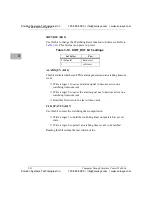
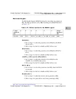
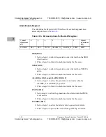
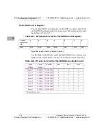
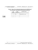
Flash BIOS Control Register
Use the Flash BIOS Control Register (FLBCTRL) to control which bank
on the BIOS flash memory part is to be accessed. Bits written can also read
back. Refer to
BC0 (Bit 0), BC1 (Bit 1) and BC2 (Bit 2)
Use the Bank Control bits to control the Flash BIOS device. Reset selects
Bank 0 as the default. Refer to
for Bank Control bit settings.
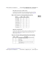
Table 3-21. Bit descriptions for the Flash BIOS Control register
7 (most
significant
bit)
6
5
4
3
2
1
0
RES
RES
RES
RES
RES
BC2
BC1
BC0
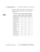
Table 3-22. Bit selections for the Flash BIOS Device Bank Control
512K
BANK
Flash
Offset
Window
BC2
BC1
BC0
Bank 0*
000000h
FFF80000h
0
0
0
Bank 1
080000h
FFF80000h
0
0
1
Bank 2
100000h
FFF80000h
0
1
0
Bank 3
180000h
FFF80000h
0
1
1
Bank 4
200000h
FFF80000h
1
0
0
Bank 5
280000h
FFF80000h
1
0
1
Bank 6
300000h
FFF80000h
1
1
0
Bank 7
380000h
FFF80000h
1
1
1
*Default Reset state
Solution Systems Technologies Inc.
720-565-5995 | [email protected] | www.solusys.com
Solution Systems Technologies Inc.
720-565-5995 | [email protected] | www.solusys.com


