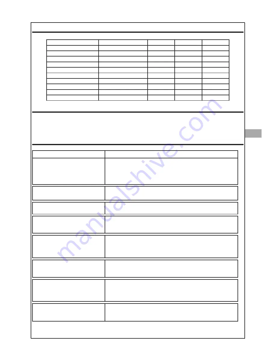
Solter aeroprocess 2000 Instruction Manual Download Page 41

ROLLERS

FAULTS

In the event of any fault that may be hazardous to people, the machine and/or the environment, you must disconnect
the machine immediately and make sure it cannot be reconnected until the problem that caused the fault has been
solved. Faults should only be eliminated by qualified personnel, taking into account the safety instructions of the ma-
chine.

POSSIBLE ANOMALIES AND SOLUTIONS

ROLLERS

MATERIAL

2000

3200

3220

0,6 - 0,8 V groove

Fe, SS,CuSi, CuAl

56105

-

55606

0,8 - 1,0 V groove

Fe, SS,CuSi, CuAl

56106

55600

-

1,0 - 1,2 V groove

Fe, SS,CuSi, CuAl

55986

55601

55607

1,2 - 1,6 V groove

Fe, SS,CuSi, CuAl

-

55602

55608

0,8 - 1,0 U groove

Al

55987

55612

-

1,0 - 1,2 U groove

Al

55988

55603

55609

1,2 - 1,6 U groove

Al

-

-

55610

0,8 - 1,0 Knurled groove

Flux Core, Metal Core

56116

-

-

1,0 - 1,2 Knurled groove

Flux Core, Metal Core

55989

55604

55611

1,2 - 1,6 Knurled groove

Flux Core, Metal Core

-

55605

55613

ANOMALY

POSSIBLE CAUSE

The machine doesn’t start up

Verify the mains
Defective main switch.
Turn off the machine or unplug it from the mains for 1 minute and try to
start it up again.
Electronic circuit is defective.

Anomaly indicator lights up

Turn off the equipment for a minute and start it up again. If the error
persists, contact technical service.

Overtemperature indicator lights up

The machine has become overheated. Wait until the machine regains a
safe temperature.

Output indicator is flashing

The equipment has found that the torch push button was pressed du-
ring startup or when recovering from an overtemperature fault. Release
the button of the torch and/or pedal.

The wire does not come out correctly

Verify that the drive system rotates correctly.
Verify that the coil brake is not too tight.
Verify that the drive system accessories are in good conditions.
Verify that the torch and consumables are in good conditions.

The wire does not come out at the 
proper speed

At the beginning of the welding, the wire always comes out with a mini-
mum speed. Verify that the wire feeding system works properly with the
manual feeding button

.

Shielding gas doesn’t comes out

Check that there is gas in the bottle.
Check that the flow rate adjustment is correct.
Verify that torch is not pinched and / or perforated.
Gas valve defective.

The arc is not stable and the wire 
collides with the workpiece.

Check if the material used corresponds to the selected in the machine.
Verify that consumables and rollers are appropriate with the material in
use.

SOLTER

SOLDADURA S.L.

AEROPROCESS

19

EN

Summary of Contents for aeroprocess 2000

Page 1: ...READ THIS MANUAL BEFORE STARTING THE EQUIPMENT MANUAL DE INSTRU ES INSTRU ES PARA O USO E MANUTEN O LEIA ESTE MANUAL ANTES DE UTILIZAR O EQUIPAMENTO BEDIENUNGSANLEITUNG BEDIENUNGS UND WARTUNGSANLEITUN...

Page 2: ...3200 7 Puesta en servicio Aeroprocess 3220 7 Esquema panel frontal 9 Operativa panel 10 Simbolog a del display 11 Operativa del men 12 Operativa soldadura MIG MAG 13 Operativa soldadura MMA 15 Operati...

Page 3: ...que las part culas que se desprendan entren en contacto con la piel No apunte con la antorcha a ninguna parte del cuerpo PROTECCI N DE LOS OJOS Los soldadores y sus ayudantes deben utilizar gafas de s...

Page 4: ...ura con electrodo revestido MMA el equipo est equipado con las funciones de anti stick hot start y arcforce ajustables Al emplear estas funciones el equipo permite soldar eficazmente cualquier tipo de...

Page 5: ...ess 2000 Aeroprocess 3200 Aeroprocess 3220 Voltaje de entrada U1 230V 15 400V 15 400V 15 Intensidad m xima de entrada I1 m x 37A 22 2A 22 2A Voltaje de soldadura en vac o U0 68V 64V 64V Potencia absor...

Page 6: ...el ctricas El interruptor autom tico se debe elegir en funci n de la placa de caracter sticas del equipo Se aconseja un interruptor con una relaci n intensidad tiempo del tipo lenta curva D para preve...

Page 7: ...a 25m Estos datos son como referencia y pueden NO adaptarse a todas las aplicaciones Si el cable se sobrecalienta utilice una secci n de cable mayor CONEXIONADO DE LA ANTORCHA Conectar la antorcha MIG...

Page 8: ...ma de corriente dis ponga de la conexi n de tierra La tensi n de la red debe encontrarse dentro de los m rgenes establecidos por Solter Soldadura 230V 15V Fuera de estas tensiones la m quina puede fun...

Page 9: ...conecta al polo negativo y la pinza de masa al polo positivo Se recomienda consultar las especificaciones de polaridad especificadas por el fa bricante de alambre ya que podr an variar La devanadora A...

Page 10: ...11 Tiempo 0 1s 12 Voltios 13 Porcentaje 14 Din mica del arco inductancia 15 DISPLAY de valores 16 DISPLAY de par metros 17 Selector del Men 18 Pulsador de enhebrado manual 19 Mando principal 20 Select...

Page 11: ...dad del alambre D Panel indicador principal En sta pantalla se indicaran todos los valores que seleccionemos variables de solda dura opciones del men as como los valores de corriente y tensi n del pro...

Page 12: ...a en MIG Tiempo de repetici n en MIG Control de penetraci n en MIG Din mica de la soldadura en MIG Men de datos Tiempo trabajado Acceso a programas Guardar programa en la memoria Recuperar programa de...

Page 13: ...mo secundarios Para gestionar la lectura escritura de estos progra mas debemos seleccionar el men programa en trar en el modo men y seleccionar Pro Ahora podemos seleccionar entre la opci n de recuper...

Page 14: ...n con el tensor al m ximo indicar a que existe un problema en el sistema de arrastre Deber an comprobarse la gu a del alambre sirga el ajuste del freno el estado de la punta de contacto y el desgaste...

Page 15: ...ensi n de soldadura para el material utilizado Modo sin rgico En este modo deberemos especificar en el equipo el tipo de material grosor del alambre y gas de protecci n que vamos a utilizar Una vez co...

Page 16: ...menor potencia de soldadura PtG Tiempo de post gas Determina el tiempo que se suministrara gas despu s de finalizar la soldadura Los valores posibles son de 0 1 a 5 0 segundos PrG Tiempo de pre gas Ti...

Page 17: ...oprocess 2000 o 3220 o el adaptador ref 56210 todos los modelos para antorchas TIG SR17 o SR26 en este caso se conectar la antorcha directamente a los bornes externos Se deber utilizar gas Arg n 100 L...

Page 18: ...trar m s en la ra z de la soldadura En funci n del amperaje a utilizar se recomienda afilar mas o menos el elec trodo En funci n del amperaje al que vaya a soldar se recomienda un di metro de electrod...

Page 19: ...desee manipular la unidad Aerofeed utilice el asa de transporte Dicha asa debe utilizarse en caso que quiera colgar en alto la devanadora El asa de la unidad debe estar aislada el ctricamente de la e...

Page 20: ...rcuito electr nico defectuoso Piloto de anomal a iluminado Apagar el equipo un minuto y ponerlo en marcha de nuevo Si el error persiste contactar con el servicio t cnico Piloto de sobretemperatura ilu...

Page 21: ...OLUCI N Er 1 Datos de la memoria corruptos ste error se recupera autom ticamente Se cargar n los datos por defecto Enviar el equipo al servicio t cnico para una puesta a punto Er 2 Error de la memoria...

Page 22: ...ito de soldadura Limpie la unidad de arrastre con aire comprimido Trimestral Sople el t nel de ventilaci n con aire a presi n seco desde la toma de ventilaci n frontal No remueva el envolvente de prot...

Page 23: ...Commissioning of Aeroprocess 3220 7 Front panel layout 9 Operating the front panel 10 Symbology of the display 11 Operating the menu 12 MIG MAG welding operations 13 MMA welding operations 15 TIG weld...

Page 24: ...s and their assistants must use safety masks or goggles with filters which stop harmful radiation entering the eyes Use special screens to observe the welding area during the process FIRE PROTECTION T...

Page 25: ...with adjustable anti stick hot start and arc force features Thanks to these features you can weld effectively with any type of coated electrodes For TIG welding the equipment allows Lift Arc ignition...

Page 26: ...0V 15 Maximum input current I1 m x 37A 22 2A 22 2A No load voltage U0 68V 64V 64V Max absobed power 9KVA 9KVA 9KVA Fuse 25A 20A 20A Mig Mag regulation range 30 200A 30 320A 30 320A MMA regulation rang...

Page 27: ...irect or indirect contacts with electri cal parts The automatic switch must be chosen according to the equipment nameplate A switch with an intensity time ratio of the slow type D curve is recommended...

Page 28: ...cycle for lengths of less than 25m These data are for reference and may NOT suit all applications If the cable overheats use a larger cable section CONNECTION OF THE TORCH Connect the MIG torch in it...

Page 29: ...that the voltage is within the range of 230Vac 15 Outside this voltage range the machine may mal function Depending on the type of welding that is going to be used MMA TIG MIG MAG you must connect the...

Page 30: ...asic type The power cable is connected to the negative pole and the earth clamp to the positive pole You are recommended to see the polarity specifications given by the wire manufac turer as these may...

Page 31: ...Time 0 1s 12 Volts visualization 13 Percentage 14 Arc dynamics inductance 15 Values display 16 Parameters display 17 Menu selector 18 Button of manual feeding 19 Main selector 20 Synergic or manual s...

Page 32: ...MANUAL mode you can adjust the welding voltage and speed indepen dently D Main panel displays These displays show all the values selected welding variables menu options and the cu rrent and voltage va...

Page 33: ...g in MIG Welding time in MIG Repetition time in MIG Penetration control in MIG Arc dynamics in MIG Data menu Worked time Program access Save program in memory Load program from memory Menu for welding...

Page 34: ...s select the program menu enter menu mode and select Pro After that you can choose between the options read a program L P or save a pro gram S P Having selected the option select the program number wi...

Page 35: ...ward At that point give half more turn to the tensor 6 If the wire continues skidding even with the maximum pressure this indicates that there is a problem in the wire feeding system You should check...

Page 36: ...he material used must be known Synergic Mode In this mode we have to specify the material type wire diameter and shielding gas that we are going to use After set ting up the machine it will adjust its...

Page 37: ...a ture PtG post gas time Determines the time that gas will be supplied after the end of welding The possible values are from 0 1 to 5 0 seconds PrG pre gas time Time during which gas is supplied befor...

Page 38: ...and 3220 or the TIG adapter ref 56210 all models for SR17 and SR26 TIG torches In this case the torch has to be connected directly to the external terminals You must use Ar 100 The torch polarity has...

Page 39: ...ore energy can be con centrated at the weld root Depending on the amperage used it is recommended to sharpen the electrode with a gre ater or lesser extent Depending on the amperage used to weld a spe...

Page 40: ...want to manipulate the Aerofeed unit use the carrying handle This handle must be used if you want to hang up the winder The handle of the unit must be electrically insulated from the metal structure...

Page 41: ...n off the equipment for a minute and start it up again If the error persists contact technical service Overtemperature indicator lights up The machine has become overheated Wait until the machine rega...

Page 42: ...a memory This error is solved automatically The default data will be loaded Send the equipment to the technical service for an overhaul Er 2 Internal error in the memory This error is solved automatic...

Page 43: ...f the welding circuit Clean the wire feeder unit with compressed air Quarterly Blow the ventilation tunnel with compressed air dry from the front intake vents Don t re move the vents during the operat...

Page 44: ...AEROPROCESS 2000 AEROFEED 5 69000271 SOLTER SOLDADURA S L AEROPROCESS A1...

Page 45: ...AEROPROCESS 3200 SOLTER SOLDADURA S L AEROPROCESS A2...

Page 46: ...AEROPROCESS 3220 SOLTER SOLDADURA S L AEROPROCESS A3...

Page 47: ...SOLTER SOLDADURA S L AEROPROCESS A4...

Page 48: ...SOLTER SOLDADURA S L AEROPROCESS A5...

Page 49: ...SOLTER SOLDADURA S L AEROPROCESS A6...

Page 50: ...SOLTER SOLDADURA S L AEROPROCESS A7 SOLTER SOLDADURA S L AEROPROCESS A7...

Page 51: ...ie Seriennummer ALL NUMBERS Is in compliance with the directives Es conforme a las directivas Es conforme a les di rectives Il est conforme aux directives de acordo com as directivas Entspricht den Ri...

Page 52: ...http www solter com es condiciones garantia 2 mas 1 ESPA OL Para detalles de garant a fuera de Espa a contacte con su distribuidor local ENGLISH For details of guarantee outside Spain contact your loc...

Reviews: