background image

ORIGIN User Guide

Console Overview

3

ORIGIN Channel Strip

Channel Strip Overview

An overview of the ORIGIN Channel Strip features.

Section descriptions are in the following pages.

Channel Input typically feeds Small Fader Path for 

recording, with versatile switchable Mic/Line pre-amp 

featuring up to 70 dB of Gain, 48 V and Polarity Invert. 

Drive provides a way to change the ultra clean linear pre-

amp to one with gentle warmth from harmonic distortion 

and transient compression artefacts. Large Fader (LF)/

Small Fader (SF) Path indicator and flip switch allows use 

of Drive circuit for Mixdown through Large Faders.

Line Level Monitor Input with Gain Trim, typically feeds 

the Large Fader and is used with discrete DAW feeds 

for analogue summing or record signal monitoring. The 

Path Flip switch allows the Monitor Input to feed the 

Small Fader.

Channel Direct Output provides the cleanest record path 

to the recorder and frees track buses for more creative 

use. It also provides a simple way to record post fader 

paths to a DAW to 'print' Mix Stems.

The Pre Fader selection and LF/SF Path indicator/flip 

switch allow for versatile path source selection.

Two Stereo Cue feeds (A and B), with Level Control and 

Pan. Typically sent pre Large Fader to provide foldback 

mixes that follow the control room Large Fader monitor 

mix, the SF switch sources the feed from Small Fader 

and Post Fader feed option allow use as additional 

Stereo FX sends.

Four Mono Aux buses with Level control provides a 

simple way to feed mixes to external effects or create 

mono parallel mixes for additional bus needs. SF switch 

to source Aux from Small Fader path and Pre Fader feed 

option for creating mono foldback sends.

18 dB/oct High Pass Filter (HPF) sweeps from 10 Hz 

to 400 Hz with IN switch and LF/SF Path indicator/flip 

switch.

SSL E-Series ‘242’ EQ circuit

Four Band Parametric EQ with variable Cut/Boost per 

band.

HF and LF bands have Bell switches to change from 

shelving curves to bell curves for additional EQ sculpting. 

HMF and LMF bands have separate Q controls to adjust 

bell curve bandwidth in addition to gain and frequency.

IN switch for true circuit bypass.

LF/SF Path indicator/flip to switch path for the EQ.

Compact and sophisticated BUS/Channel Routing

ROUTE switch activates routing.

Blue LED indicates if channel routed to bus.

FOLLOW PATH PAN allows stereo odd/even bus 

panning.

LF/SF Path indicator/flip switch.

OVERLOAD LED illuminates when Large or Small fader 

paths within 3 dB of either path's clipping point monitored 

pre Large and Small Fader, post processing.

Small Fader (SF) controls.

60mm high quality audio fader.

SF Pan with centre detent.

SF from LF sources feed from Large Fader.

0 dB switch bypasses fader to set unity gain.

INS IN switch SF Insert into Small Fader path.

INS PRE switches SF Insert pre fader.

SF TO MIX routes the Small Fader path to the MIX BUS.

SOLO and CUT for Small Fader path.

Large Fader (LF) controls.

100 mm high quality audio fader (not shown).

LF Pan with centre detent.

0 dB switch (not shown) bypasses fader to set unity gain.

INS IN switch LF Insert into Large Fader path.

INS PRE switches LF Insert pre fader.

LF TO MIX routes the Large Fader path to the MIX BUS.

SOLO and CUT for Large Fader path (not shown).

Summary of Contents for ORIGIN

Page 1: ...www solidstatelogic com ORIGIN User Guide ...

Page 2: ...tion may be reproduced in any form or by any means whether mechanical or electronic without the written permission of Solid State Logic Oxford OX5 1RU England As research and development is a continual process Solid State Logic reserves the right to change the features and specifications described herein without notice or obligation Solid State Logic cannot be held responsible for any loss or dama...

Page 3: ...ronic architecture and precision bargraph meters make it a perfect partner for the highest quality convertors and DAWs in the most professional production applications A unique and innovative modular centre section allows ORIGIN to adapt to different applications and priorities whether being used as a purely tracking console with additional boutique analogue additions to the 19 rack centre section...

Page 4: ...lter HPF 8 ORIGIN 9 Path Block Diagram 9 ORIGIN EQ Curves 10 ORIGIN 11 Path Block Diagram 11 BUSES LF or SF Path routing to Track Buses 12 Small Fader SF Section 14 Small Fader SF 14 SF PAN 14 SF FROM LF 14 0dB 14 Small Fader Insert 14 Insert In INS IN and Insert Pre INS PRE 14 SF TO MIX 14 SOLO and CUT 14 Large Fader LF Section 15 Large Fader LF 15 LF PAN 15 Large Fader Insert 15 Insert In INS IN...

Page 5: ...MON SOURCE 31 PEAK MODE SELECT 31 PEAK CLEAR 31 DIM CHAN METERS and DIM BUS METERS 32 DIM MON METERS and DIM MIX METERS 32 OSCILLATOR 32 400 Hz ON and EXT IN 32 OSC LEVEL 32 TO MIX and TO BUSES 32 The MISC Section 32 SHIFT CLEAR ROUTE 32 Power Management Tools 33 Appendix A ORIGIN Advanced Routing 34 Routing Terms 34 From Channel Routing The typical approach for Analogue Consoles 34 Simple Channel...

Page 6: ...remental Routing Setup 39 Factory Setup Reset 40 To perform a Factory Reset 40 Appendix C Performance Specification 41 Audio Performance 41 PureDrive Channel Input Microphone Line Amplifier 41 Monitor Input Line Input Amplifier 41 Channel Equaliser 42 Overall Channel Signal Chain Specifications 42 Crosstalk 43 Overall Console Noise 43 Environmental Requirements 43 Appendix D ORIGIN Block Diagram 4...

Page 7: ... A new PureDrive mic pre inherits the clarity and purity of previous SSL Mic Pre designs that can also switch to a warm harmonically rich and driven tone that varies with mic pre gain when the Drive function is activated A new mix bus and mix amp architecture delivers an amazingly low noise floor and huge headroom along with SSL s latest summing bus technology that retains the classic SSL sound wh...

Page 8: ...ic com Safety Notices IMPORTANT Please read the safety notice information included in the Safety Guide supplied inside the box before using ORIGIN Dimensions Approx Dimensions in mm and feet inches are shown in these diagrams Other specs are Approximate Weight 330lb 150kg including optional legs Approximate Power Consumption Typically 900 Watts 1200 Watts maximum when on Typically 40 Watts when in...

Page 9: ...o external effects or create mono parallel mixes for additional bus needs SF switch to source Aux from Small Fader path and Pre Fader feed option for creating mono foldback sends 18 dB oct High Pass Filter HPF sweeps from 10 Hz to 400 Hz with IN switch and LF SF Path indicator flip switch SSL E Series 242 EQ circuit Four Band Parametric EQ with variable Cut Boost per band HF and LF bands have Bell...

Page 10: ... pre amp gain 2 dB to 70 dB or the Line amp gain 12 dB to 55 dB depending on the selected input source The Mic input s nominal impedance is 1 5 kΩ and includes a ø polarity switch and switched 48V phantom power DRIVE switch The DRIVE switch significantly changes the character of the pre amp and how it reacts to signal level The default ORIGIN mic pre is a very clean linear design which has no dist...

Page 11: ...t feeds the Large Fader LF path This is indicated by the red and green LEDs that bridge the line between these two sets of input controls This default routing can be swapped by using the PATH FLIP switch When this switch is pressed the red and green LEDs also flip status to show the path routing of the input sections This philosophy is repeated through the channel strip sections i e RED LED Small ...

Page 12: ...e Small Fader SF path as indicated by the red and green SF and LF LEDs This default routing can be swapped by using the PATH FLIP switch The Channel Direct Out provides the cleanest record path to the recorder and frees track buses for more creative use It also provides a simple way to print post fader paths to a DAW to print Mix Stems simplifying mix revisions CHAN IN dBu 24 23 22 21 20 19 18 15 ...

Page 13: ... to each bus a traditional SSL compromise between typical mono 3 and 6 dB centre points for constant perceived level or power Mono Auxilliary Aux Sends Each channel can access four mono Aux sends 1 to 4 with independent level controls By default the Aux sends are fed from the Large Fader path post fader post insert but can be switched to Pre Fader post Insert by engaging the corresponding PRE swit...

Page 14: ... The Parametric Equaliser in ORIGIN is based on the original SL4000E Series 242 equaliser design i e SSL s classic Black Knob EQ The individual bands function as follows HF high frequency 12 dB Octave shelving equaliser switchable to fixed Q parametric BELL HMF high frequency parametric mid band equaliser with continuously variable Q control LMF low frequency parametric mid band equaliser with con...

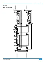
Page 15: ...iled Channel Description 9 PRE IN LF INSERT IN FLIP PRE IN FLIP PATH PATH FLIP PATH IN HPF EQ BELL BELL LF HF Hz to LARGE FADER to SMALL FADER from MONITOR INPUT from CHANNEL INPUT SF INSERT HPF EQ ORIGIN Path Block Diagram ...

Page 16: ...ORIGIN User Guide Detailed Channel Description 10 HF Shelf HF Bell HMF Min and Max Q ORIGIN EQ Curves LMF Min and Max Q LF Shelf LF Bell ...

Page 17: ...iled Channel Description 11 PRE IN LF INSERT IN FLIP PRE IN FLIP PATH PATH FLIP PATH IN HPF EQ BELL BELL LF HF Hz to LARGE FADER to SMALL FADER from MONITOR INPUT from CHANNEL INPUT SF INSERT HPF EQ ORIGIN Path Block Diagram ...

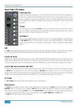
Page 18: ...RIM MASTERS AND ROUTING section in the centre section of the console In simple terms there are two ways to route signals to track buses in ORIGIN Routing from a Path to a Bus or Buses The first more traditional way is to press the ROUTE switch in the BUSES section on the channel strip you wish to route from The ROUTE LED in the channel will flash to show that it has been selected The switches in t...

Page 19: ...ight blue You can select multiple Paths e g channels 1 2 3 4 5 6 7 8 which will mean that channels 1 to 8 will be routed to Bus 1 You can now press the selected bus switch again or press the SHIFT CLEAR ROUTE switch to escape routing mode Now any path or bus that has at least one path route will have its routing LED dimly lit Channel Strip Bus routing options PATH FLIP The default channel strip to...

Page 20: ... Insert ORIGIN has a separate fully balanced Insert for both the Large Fader and Small Fader paths The primary use of the insert is to bring external processing into the signal path For example to insert a dynamics unit such as those found in SSL s 500 series modules In conjunction with an automatable level control e g SSL Sigma they can also be a way to automate the path level Insert In INS IN an...

Page 21: ... SSL consoles the Insert Send is always active while the Insert Return switches into the signal path using the INS IN switch Typically the send is Post path processing the INS PRE switch moves this point to Pre path processing The channel insert sends and returns are found on the rear panel 25 way D Type connectors Typically these are wired to a patchbay for ease of use with other external devices...

Page 22: ...etailed Channel Description 16 PRE IN LF INSERT IN FLIP PRE IN FLIP PATH PATH FLIP PATH IN HPF EQ BELL BELL LF HF Hz to LARGE FADER to SMALL FADER from MONITOR INPUT from CHANNEL INPUT SF INSERT HPF EQ Path Block Diagram ...

Page 23: ...ORIGIN User Guide Detailed Channel Description 17 Channel Section Notes ...

Page 24: ...are connected to the 16 console Track Buses either directly via a DB 25 to DB 25 link connector or more typically via a patchbay An overview of the Track Buses and Stereo Groups is shown in the block diagram below INPUT MONO L MONO R MUTE BALANCE to 3dB 3dB to MIX SOLO SUBGROUP 1L OUT SUBGROUP 1R OUT Stereo Groups A H 0dB BUS SENDS CONNECT TO STEREO GROUP IPs VIA DB 25 LINK OR HALF NORMALLED PATCH...

Page 25: ...t buffers into the Stereo Groups there is Mono switching which allows a Mono signal to be split to both left and right channels through the Stereo Group The MONO L switch takes the left signal and sends it to left and right channels the MONO R switch takes the right signal and sends it to left and right channels If both MONO L and MONO R switches are pressed both left and right paths are summed in...

Page 26: ...s Peak Clear for all console LED Meters Mix Meter Follow Monitor Source option increases main mix meter flexibility Independent DIM controls for path Channel and Monitor Inputs reduce meter distractions in busy sessions CUE and AUX Masters Master Output Trims and AFL Switches for Stereo Cue A and B buses plus mono Aux Buses 1 to 4 Stereo Returns Stereo Return Inputs with ability to route to Mix an...

Page 27: ...dback A Typically this is used to add an external effect such as reverb to an artists headphone feed TO F BACK B In the same way as the previous control this feeds the Stereo Return signal to Foldback B LEVEL Controls the amount of the Stereo Return to the main stereo Mix Bus or AFL MIX Routes the Stereo Return to the main stereo Mix Bus AFL Routes the Stereo Return to the After Fade Listen AFL bu...

Page 28: ... a headphone output The section is split into three sub sections covering monitor source switching level control and audio image In addition there is a Studio loudspeaker provision for a set of artist monitors located in the recording area these are described in the Communications section on page 26 MON SOURCE A choice of five monitor sources are available with the default source being the interna...

Page 29: ...itor outputs the DIM control reduces the output of the monitor output by an amount between 3dB and 30dB as determined by the DIM LEVEL control higher up in this section Above the large level control are MUTE L and MUTE R switches to independently cut the output of the left and right monitors respectively A large MONO switch mono s the L and R output to the monitors and reduces the level by 3dB to ...

Page 30: ...s consoles The soft knee point of the compressor ie the level at which compression starts to take place is set by the THRESHOLD control 20dB This is intentionally designed to change depending on the setting of the RATIO control decreasing the RATIO setting lowers the effective threshold hence maintaining the perceived loudness of the compressed signal The RATIO switch has six settings 1 5 1 2 1 3 ...

Page 31: ...re is a switch in the METERS controls in the Master Section see page 31 which changes the MIX Meter to follow the monitor source selection pre Monitor Level Control but post AFL PFL selection This provides a useful way to meter other sources on the MIX meter or meter selections from AFL PFL Another useful use for this meter is monitoring setting Oscillator levels as this meter is fed directly when...

Page 32: ...ntrol in the CUES AND AUX MASTERS section page 29 TALKBACK and LISTEN LEVEL Controls Under each column of the source selection switches there is a master level control for the three destinations The STUDIO output control is identified with a RED cap with the Foldback outputs identified in BLUE Details about the Talkback and Listen Mic inputs can be found later in the guide page 29 AFL After Fade L...

Page 33: ...essing and holding the TALK ALL switch and simultaneously pressing the LISTEN switch When the TALK ALL switch is released the LISTEN switch will now be linked to it Repeating this operation will unlink the function SEND LISTEN TO TALKBACK This feature connects together the Talkback and Listen Mic signals to allow a simple conference system This can be useful where the Listen Mic is a convenient wa...

Page 34: ...gram above This allows an externally amplified Mic Pre signal to be fed through the Talkback Mic Compressor This is the same circuit as the infamous SSL Listen Mic Compressor With the SWITCHED EXT TB OUT switch pressed in the COMMUNICATIONS part of the Master Section there is a Talkback Mic output signal on the MAIN MIX OP INS SEND DB 25 rear connector and on the patchbay if connected this gives a...

Page 35: ...iel s Intruder snare sound fame There is a Listen Mic output signal on the F B MISC OUT DB 25 rear connector and on the patchbay if connected This gives an input and output path to use this compressor creatively If you are using this feature don t forget to disconnect or over patch the Listen Mic Amp connections to prevent the Listen mic signals being summed with the external Listen Line input CUE...

Page 36: ...connections for both the Large Fader and Small Fader paths SOLO LINK active is indicated by a green LED at the intersection of the lines linking the SIP functions For SOLO LINK to be active both LF SIP and SF SIP switches must be in the same mode i e both pressed or both unpressed if one of these is not pressed the LED will not illuminate and SOLO LINK will not be active SOLO ACTIVE and SOLO CLEAR...

Page 37: ...h repeated pressing The options are No Peak Hold The meter displays instantaneous peak values only First Press 1 second Peak Hold Peak level LED stays illuminated for approximately 1 second and then automatically resets This mode can be identified when selected by the red 24dBu LEDs illuminating for approx 1 second and then falling to the current metered level Second Press 3 second Peak Hold Peak ...

Page 38: ...al input TO MIX and TO BUSES These switches send the Oscillator or EXT IN signal to the 16 track buses TO BUSES or the stereo Mix bus TO MIX Either of these selections over ride the default signals being fed to the respective outputs so take care not to press them when recording from these outputs The MISC Section ORIGIN s MISC section is the home for a variety of functions SHIFT CLEAR ROUTE The b...

Page 39: ...h simple switches for this useful feature AUTO SLEEP and WAKE SLEEP Origin can be put into Sleep mode by pressing and holding the WAKE SLEEP switch for approximately 3 seconds When the console is in Sleep mode the WAKE SLEEP LED will pulse smoothly at about 1 pulse per second The console can be awoken from Sleep by pressing the WAKE SLEEP switch When the console enters Sleep mode it carries out a ...

Page 40: ...can be routed to From Channel s Routing starting with the Channel or Channels and routing TO a Track Buses or Track Buses To Bus es Routing starting with the Track Buses or Track Buses and routing FROM a Channel or Channels From Channel Routing The typical approach for Analogue Consoles In a typical older analogue console the routing from channels to buses is done with routing switches in the chan...

Page 41: ...g select switches allows ORIGIN to provide a second way to route to Track Buses This starts from the bus not from the Channel and in some ways is more logical once the principles are understood Fundamentally with this way of routing it starts with putting the Track Bus into Select Mode so routing starting with the Track Bus not the Channel Simple Track Bus from Channel Routing Starting with the si...

Page 42: ...Selection of Track Buses 1 and 2 again or more simply press the Master Section SHIFT switch to escape from Range Selection mode Interrogating Routing Finding Out What Is Routed Where Finding out what signals are routed where is a simple switch press away Where Is This Channel Routed If a Channel ROUTED TO BUS LED is dimly illuminated in Idle Mode normal operating mode then it means that Channel is...

Page 43: ...l 1 ROUTE key Channel 1 now selected blinking Press and hold Channel 16 ROUTE key Channel 1 to Channel 16 now selected all blinking Keep holding both switches down for 3 to 5 seconds Channel 1 to Channel 16 ROUTE LEDs will blink faster 1 to 1 incremental routing is made for the selected range NOTE This incremental routing will override any existing Channel to Bus routes for the selected range Addi...

Page 44: ... timeout in binary format with the left most LED 1 showing the least significant digit and the right most LED 4 the most significant digit Each Binary number from 1 to 1111 is a 5 minute interval So the AUTO SLEEP timing is represented by the following table Bus LED Time Until SLEEP 1 2 3 4 Minutes 15 seconds 5 10 15 20 25 30 35 40 45 50 55 60 65 70 75 For example the LED combination in the pictur...

Page 45: ... independent of Main ALT 1 ALT 2 monitor selection Default ALT 3 intercancels with Main ALT 1 ALT 2 monitor selection Automatic Incremental Routing Setup This Setup option controls the behaviour of the Automatic Incremental Routing feature See page 37 This is another setting accessed with a simultaneous press of the SHIFT and AUTO SLEEP keys to access the setup menu and with the Bus 6 key LED sele...

Page 46: ...ep state Any Setting Monitor and Source Selection To perform a Factory Reset Power up the console either from off or from Sleep state Press and hold PEAK MODE SELECT DIM MON METERS switches during and for the duration of the meter start up sequence which happens during power up Red Peak LEDs on every meter will start flashing which means that the Factory Reset has been performed Release the switch...

Page 47: ... Mic Amp Gain Variable from 2 dB to 70 dB Line Amp Gain Variable from 12 dB to 55 dB Input Impedance 1 4 kΩ Max Input Level 1 THD Mic Amp 21 dBu Output Headroom 26 5 dBu at onset of clipping Frequency Response 20 Hz to 20 kHz 3 dB high rolloff 0 0 2 dB 90 kHz THD Noise 10 dBu applied 30 dB gain 1 kHz filter 22 Hz to 80 kHz 0 004 at 1 kHz 0 018 at 10 kHz CMRR 10 dBu applied 30 dB gain 57 5 dB 20 Hz...

Page 48: ...d routed to specified output by shortest path All controls set flat out or at unity gain as appropriate Pan set to full left or right Measurement Conditions Value Auxiliary Send Track Bus and Main Mix Bus Outputs Output Headroom into 600Ω at onset of clipping into 10kΩ at onset of clipping 24 dBu 26 5 dBu THD Noise 20dBu 1kHz filter 22Hz to 80kHz 0 0008 at 1 kHz 0 0008 at 10 kHz Frequency Response...

Page 49: ...m one under test Channel not routed 64dB from 20 Hz to 20 kHz 113dB from 20 Hz to 20 kHz Mic Input 50dBu applied to Mic Input at maximum gain measured at Direct Output Monitor path selected 95 dB Overall Console Noise Measured at main outputs channels routed as required with pans balance controls centred using Line input with termination All controls set flat out or at unity gain as appropriate ch...

Page 50: ...o Monitor Section TALK F BACK AR OUT F BACK BL OUT F BACK BR OUT TALK TALK ALL to 0dB TALKBACK LEVEL to 0dB SLATE LISTEN LEVEL to 0dB IN BUS COMP MIX L OUT MIX R OUT AFL L AFL R PFL MAIN L OUT MAIN R OUT ALT 1 ALT 1L OUT ALT 1R OUT ALT 2 ALT 2L OUT ALT 2R OUT ALT 3 ALT 3L OUT ALT 3R OUT MAIN CUT L CUT R 1 POL 3dB MONO LISTEN POWER CUT P AFL LISTEN iJACK L R EXT 1 EXT 1L EXT 1R EXT 4 EXT 2 EXT 3 EX...

Page 51: ...FROM LF SF TO MIX SOLO CUT SF LF PAN R L LF INS IN INS PRE LF LF SF SF LF SF SF PRE PRE 48V PRE GAIN TRIM POST SF PAN PAN POST SF PRE DRIVE ST CUE A ST CUE B AUX1 AUX3 SF PRE SF SF PRE AUX2 AUX4 0 20 20 0 dB dB 70 2 55 12 CHAN LINE PATH FLIP MON PATH FLIP DIRECT OUT R L R L LF SF IN BELL BELL IN EQ 0 dB 0 dB 0 dB 0 dB PATH FLIP 400 10 Hz HPF HF 16 1 5 kHz 10 5 HMF Q 7 6 kHz 4 5 1 5 PATH FLIP LF SF...

Page 52: ...10 0 0 0 0 0 0 0 0 20 20 0 d B 20 20 0 d B 20 20 0 d B INPUT TRIM TO F BACK A TO F BACK B ROUTED TO BUS 20 20 0 d B INPUT TRIM TO F BACK A TO F BACK B ROUTED TO BUS 20 20 0 d B INPUT TRIM TO F BACK A TO F BACK B ROUTED TO BUS 20 20 0 d B 3 30 d B d B 0 0 0 AUTO SLEEP WAKE SLEEP MAKEUP dB 20 20 20 0 10 10 10 0 d B 10 10 0 d B 10 10 0 d B 10 10 0 d B 10 10 0 d B 10 10 0 d B 10 10 0 d B 10 10 0 d B 1...

Page 53: ...0 0 10 15 20 30 40 50 10 MONO L MONO R BALANCE SOLO CUT 0 dB MONO L MONO R BALANCE SOLO CUT 0 dB MONO L MONO R BALANCE SOLO CUT 0 dB MONO L MONO R BALANCE SOLO CUT 0 dB MONO L MONO R BALANCE SOLO CUT 0 dB MONO L MONO R BALANCE SOLO CUT 0 dB MONO L MONO R BALANCE SOLO CUT 0 dB MONO L MONO R BALANCE SOLO CUT 0 dB A B C D E F G H ST GRP 15 16 ST GRP 13 14 ST GRP 11 12 ST GRP 9 10 ST GRP 7 8 ST GRP 5 ...

Page 54: ...28 29 30 31 32 H 1 2 3 4 5 6 7 8 9 10 11 12 13 14 15 16 17 18 19 20 21 22 23 24 25 26 27 28 29 30 31 32 1 2 3 4 I Tb Lm 1 2 3 4 5 6 7 8 9 10 11 12 13 14 15 16 17 18 19 20 21 22 23 24 25 26 27 28 29 30 31 32 In In 1 2 3 4 J Tb Osc Lm 1 2 3 4 5 6 7 8 9 10 11 12 13 14 15 16 17 18 19 20 21 22 23 24 25 26 27 28 29 30 31 32 L R L R op op op K TbL LmL 1 2 3 4 5 6 7 8 9 10 11 12 13 14 15 16 17 18 19 20 21...

Page 55: ...49 ORIGIN User Guide Notes Notes ...

Page 56: ...www solidstatelogic com ...

Reviews: