BiG SiX User Guide
Console Overview
12
Monitor section
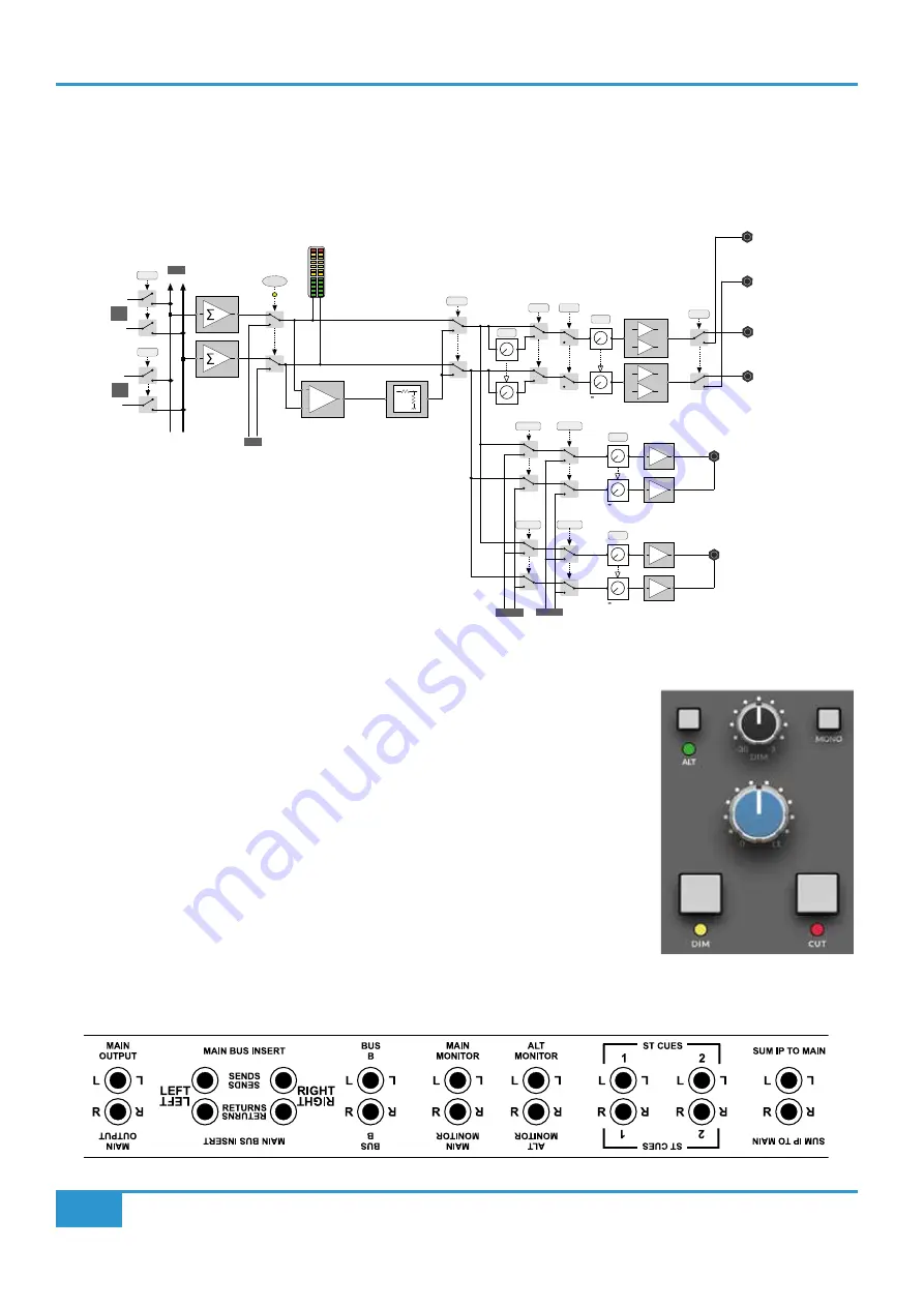
The monitoring facilities in BiG SiX are very comprehensive given the size of the console. The block diagram below shows the
structure of the Main Monitor, Alternate Monitor and Headphone outputs.
ALT
DIM
MAIN
BUS B
L R
L R
MIX
L R
MON
PFL
3dB
+
MONO
CUT
-3 to -30dB
LEVEL
to 0dB
LEVEL
+
-
+
-
ALT MON
L
R
Headphone Jack 1
ST CUE 2
ST CUE 1
to 0dB
LEVEL
PHONES 1
MONITOR
MON SOURCE
MAIN MON
L
R
Headphone Jack 2
ST CUE 2
ST CUE 1
to 0dB
LEVEL
PHONES 2
L R
MIX
L R
ST CUE 1
L R
MIX
L R
ST CUE 2
L R
MIX
L R
PFL
MAIN
BUS
BUS
B
MAIN and ALT monitor outputs
The monitor section has two sets of balanced outputs for loudspeakers labelled MAIN MONITOR
and ALT MONITOR (See rear connector layout below). By default, the MAIN MONITOR output
is used. Pressing the ALT key on the front panel switches the Monitor feed to the ALT MONITOR
output. Both Main and Alt outputs use balanced ¼” jack Sockets on the rear connector panel.
The Monitor outputs are Off when the Monitor Level is fully anti-clockwise (0) and at unity when
fully clockwise (11).
Below the Monitor Level control are buttons for DIM and CUT. The CUT button mutes all of the
monitor outputs. The DIM button lowers the monitor output level as controlled by the DIM level
knob which is directly above the Monitor Level control in the Monitor Source section.
The MONO switch sums the monitor output to Mono with a -3 dB level drop.
BiG SiX Rear Connectors
Summary of Contents for BiG SiX
Page 1: ...BiG SiX www solidstatelogic com BiG SiX User Guide ...
Page 4: ...BiG SiX User Guide This Page Is Intentionally Almost Blank ...
Page 8: ...Introduction H BiG SiX User Guide This Page Is Intentionally Almost Blank ...
Page 14: ...BiG SiX User Guide Console Overview 6 This Page Is Intentionally Almost Blank ...
Page 54: ...46 BiG SiX User Guide Notes Notes ...


