Solid State Logic 82S6XR0A0B User Manual Download Page 3

Page A-1

X-Rack Mic Amp Module

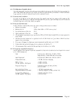
A. The Mic Amp Module

A.1 Connection

The rear panel of the module carries the Mic (‘IN’) and Line input (‘LINE’) XLRs along

with a single output (‘OUT’) XLR. The Line input and output operate at a nominal
level of +4dBu although the gain of the Line input can be varied by a front panel
control. Also contained on the front panel is an additional mono Jack socket for a high
impedance Instrument input.

A.2 Operation

The X-Rack Mic module contains three seperate input amplifiers; a Microphone
amplifier, an Instrument input and a Line input, any one of which may be selected
at any one time. A set of High and Low Pass filters are also provided.

A.2.1 MIC Section

Normally, the Microphone input on the rear of the module will be selected (‘LINE’
and ‘INST’ switches released); pressing the ‘INST’ switch selects the mono jack
instrument input on the front of the module. This is a very high impedance
unbalanced input intended to be used with guitar pickups etc. To help alleviate
‘hum’, a ground lift (‘GND LFT’) switch has been provided which places a 1k2Ω
impedance in series with the sleeve of this connector and audio ground in the
module. The gain of these inputs is continuously variable b12dB and
+75dB.

The impedance of the Microphone input can be varied between ≈1k2Ω and ≈10kΩ
by selecting the ‘IMP IN’ switch and adjusting the ‘Z’ control. This allows the
connection of line level signals to the Microphone input if required, and provides an
alternative input impedance for some dynamic microphones.

The ‘PAD’ switch reduces the signal level of both the Microphone or Instrument
inputs by 20dB. Phantom power, for microphones requiring this, can be switched on
using the ‘+48V’ switch. 

Please note that X-Rack units prior to serial number XRK0110

are 

not

normally enabled for +48V. However, a field retrofit kit (629620XR) is available for

these units. Any in-warranty X-Rack units can be upgraded free-of-charge; for units out of
warranty a charge will be made. Please contact your local distributor to order this kit, if
required.

Note. Please note that connecting a microphone to the X-Rack Mic module with phantom power

switched on is not advised as it may cause damage to either the microphone or the input
stage of the X-Rack module. Take care not to connect line level sources (keyboards etc.) to the
microphone input with phantom power switched on as this may damage the output stage of
the connected unit.

A.2.2 LINE Section

The Line input on the rear of the module is selected by pressing the ‘LINE’ switch. The gain of this input
can be varied by ±20dB from the nominal 0dB.

The Ø (Phase) switch reverses the phase of the selected input.

2

1

SEL 

XR621

MIC 

INST 

IMP 

+48V 

PAD 

LINE 

LINE 

Ø 

HF 

IN 

IN 

IN 

REC 

REC 

GND 
LIFT 

INSTRUMENT 

OUTPUT 

SIGNAL 

LF 

LO HI 

dB 

+75 

+12 

+20 

-20 

dB 

KHz 

9 6 

50 

30 4 

30 600 

60 

160 300 

IN

OUT

LINE 

1

2

Summary of Contents for 82S6XR0A0B

Page 1: ... available free of charge from your local distributor if the X Rack unit concerned is in warranty For units that are out of warranty a small charge will be made The absence of this kit is indicated by the buscard in the X Rack being a 629620X1 RE 1 rev 1 with a number of components ie IC2 C4 L4 missing For correct operation of Total Recall your X Rack unit must be running V1 1 0 or later software ...

Page 2: ......

Page 3: ...MP IN switch and adjusting the Z control This allows the connection of line level signals to the Microphone input if required and provides an alternative input impedance for some dynamic microphones The PAD switch reduces the signal level of both the Microphone or Instrument inputs by 20dB Phantom power for microphones requiring this can be switched on using the 48V switch Please note that X Rack ...

Page 4: ...C L and REC R which route the module signal onto a common internal record bus The signal present indicator measures signals immediately prior to the output amplifier It will light GREEN for output signals above the lower threshold of 60dBu AMBER for signals between 4dBu and 24dBu and lights RED for signals above 24dBu The record bus is not currently used but may be used by forthcoming X Rack modul...

Page 5: ...hted measurements are specified as 22Hz to 22kHz band limited RMS and are expressed in units of dBu All distortion measurements are specified with a 36dB Octave low pass filter at 80kHz and are expressed as a percentage The onset of clipping for headroom measurements should be taken as 1 THD Unless otherwise quoted all figures have a tolerance of 0 5dB or 5 All measurements are made with the opera...

Page 6: ...kHz 18dBu applied 28dB gain 0 05 at 10kHz Frequency Response 0 05dB 0 1dB from 20Hz to 20kHz 3dB at 150kHz Equivalent Input Noise 82dB at 12dB minimum gain Input terminated with 150Ω 88dB at 28dB gain mid position A 2 5 Line Input Performance Signal applied to Line Input and measured at Output Input Gain control set to 0dB indent Gain Continuously variable from 20dB to 20dB Input Impedance 10kΩ TH...

Page 7: ... for minimum level normally 40dBu A 4 2 Line Input Equipment Required Calibrated audio oscillator and audio level meter Test Signal 1kHz sinewave 0dBu Input and Output Oscillator to Line Input and Output to the audio level meter Unit Setup Set the Line Gain to indent 0dB and select LINE Level Trim Adjustment 1 Adjust VR6 0dB for 0dBu 0 05dB A 4 3 Output Balance Equipment Required Calibrated audio ...

Page 8: ... panels are offset Weight 260g 9 5 ounces Boxed size 190mm x 290mm x 70mm 7 5 x 11 5 x 2 5 Boxed weight 460g 16 5 ounces All values are approximate A 7 Environmental Specification As per X Rack see page 17 Instrument Input Location Front Panel Conn Type Mono 1 4 Jack Socket Pin Description Tip Guitar Input Sleeve Chassis Audio Output Location Rear Panel Conn Type XLR Male Pin Description 1 Chassis...

Reviews: