background image


SkyWay-QM: Quick Start Guide 


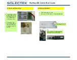
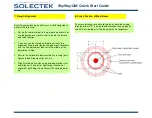
11. Fine Adjustment — Azimuth & Elevation


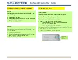
12. System Verification


For best radio link: 
 
Perform all alignments and tighten all bolts at both ends of link.  
 
Connect a PC and verify receive signal quality 
 
Follow Configuration Guide for system verification: 


• 

Access the radio unit’s GUI on your web browser: 


- Default IP address: 192.168.0.1 for Low Band radio and  


192.168.0.2 for High Band radio. 


- User name: 

admin 

Password: 

adminpass 


Note: products with Secure NMS require you to enter an additional character
(s) to the address. (ex. https://192.168.0.1). 
 

• 

Clear Statistics and verify error free operation. 

Azimuth: 
 
Refer to your antenna manufacturer’s installation guide to per-
form the following: 
 

• 

Loose azimuth lock bolts 

• 

Azimuth-adjust to capture highest RSL voltage peak. Make 
sure to identify side-lobe peaks.  

• 

Tighten azimuth lock bolts.  

Elevation: 
 
Refer to your antenna manufacturer’s installation guide to per-
form the following: 
 

• 

Loose elevation lock bolts 

• 

Move elevation adjustment to capture highest RSL voltage 
peak. Make sure to identify side-lobe peaks.  

• 

Tighten elevation lock bolts.  

Summary of Contents for SkyWay-QM

Page 1: ...upplies are optional Make sure to order them from Solectek if you do not have your own 48V power source Surge suppressors are optional and must be ordered separately V 1 1 Refer to your antenna manufacturer s installation guide to Assemble the antenna mounting kit Mount the antenna to the mast ...

Page 2: ...nting the antenna Slip fit radio over the antenna waveguide Fasten the latches at four corners 1 Install SFP modules in radio with duplex MMF or SMF fiber from the radio to the network termination equipment The cable should be looped around the inside of the enclosure to provide strain relief 2 Connect fibers at the network equipment ...

Page 3: ...ng small bladed tool to hold open contacts Ground MUST be used Attach ground lug to ground screw and tighten with 5 16 wrench 6 Antenna Alignment Align one antenna at a time Ensure azimuth lock bolts are tight while adjusting Verify power LED is lit Connect RSL test cable and place voltmeter within easy viewing ...

Page 4: ...dio terminal to the pre defined azimuth or use binoculars or a signal mirror to locate the remote end radio location If you can see the remote end radio estimate the alignment visually and tighten the pole mount brackets with the fine adjustment bolt set to the middle of the adjustment range Ensure the horizontal adjustment bolts are snug only tighten the bolts one quarter of a turn Slightly rotat...

Page 5: ... Quick Start Guide 9 Locate Center of Main Beam 10 RSL Voltage vs dBm Chart For short links if the RSL voltage is saturated there is further adjustment capability to reduce the Tx power in the NMS user interface ...

Page 6: ... Note products with Secure NMS require you to enter an additional character s to the address ex https 192 168 0 1 Clear Statistics and verify error free operation Azimuth Refer to your antenna manufacturer s installation guide to per form the following Loose azimuth lock bolts Azimuth adjust to capture highest RSL voltage peak Make sure to identify side lobe peaks Tighten azimuth lock bolts Elevat...

Reviews: