2
2. Installation Outline
This section summarizes the steps needed to properly configure and install
the SkyWay Excel Radio. As the background and guidelines for much of
the radio installation process are well covered in many in-depth
publications and training classes, only those steps that uniquely relate to
the SkyWay product are covered in this User Guide.
A. System Design
RF Design and Site Survey
IP Network Design
B. Unit Preparation
Unit connection (Section 3)
Initial Configuration (Sections 4-6)
Bench testing (Section 7)
C. Site Preparation
Selection of unit mounting location
Cable routing
Preparation of mast and other supporting structures
D. Physical Installation
Mounting (Section 8)
Antenna alignment (Section 9)
E. Verification
Link metrics (Section 10)
Ping
connectivity
Performance
testing
Reliability
monitoring
F. Optimization
RF channel tuning
Data rate tuning (see Product ‘Range Guide’)
QoS (Section 11)
G. Mana Maintenance
VLAN (Section 12)
Telnet (Section 13)
SNMP (Section 14)
Network Time (Section 15)
Password Management (Section 16)
Software upgrades (Section 17)
Reboot (Section 18)
H. Troubleshooting
Event Log (Section 19-20)
Diagnostics
(Section
21)
3. System Connection
A. P
ORT
D
ESCRIPTIONS
The SkyWay Excel has the following access ports:
•
(1) Fast Et Power Connector: RJ45 jack
•
(2) RF Ports: N type, female (connectorized unit only)
The RJ45 connector is accessed at the bottom of the unit, through a multi-
piece waterproofing feedthrough.
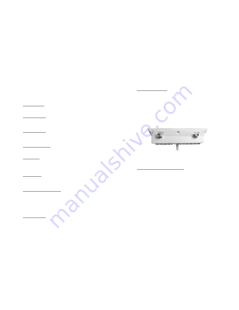
If included, the two RF Ports are accessed on the top of the unit.
Unit Top
B. C
ONNECTING THE
S
KY
W
AY
U
NIT
Using the appropriate diagram below as a guide, cable your SkyWay test
system. Connect your PC to the POE injector using (a) crossover Ethernet
cable or (b) straight cable and a hub/switch.


