background image

13

SOLARIS® SMART 54W™

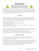
Disconnect the fixture from mains power and allow to cool completely before cleaning or 

servicing. Service fixtures in an area where there is no risk of injury from failing parts, tools 

or other materials. Excessive dust, smoke fluid, and particle buildup degrades performance, 

causes overheating and will damage the fixture. Damage caused by inadequate cleaning or 

maintenance is not covered by the product warranty.

CLEANING

The cleaning of lenses must be carried out periodically to optimize light output. Cleaning 

schedules for lighting fixtures vary greatly depending on the operating environment. It is 

therefore impossible to specify precise cleaning intervals for the fixture. Environmental fac

-

tors that may result in a need for frequent cleaning include:

• Use of smoke or fog machines.

• High airflow rates (near air conditioning vents, for example).

• Presence of cigarette smoke.

• Airborne dust (from stage effects, building structures and fittings or the natural environ

-

ment at outdoor events, for example).

If one or more of these factors is present, inspect fixtures within their first 100 hours of oper

-

ation to see whether cleaning is necessary. Check again at frequent intervals. This procedure 

will allow you to assess cleaning requirements in your particular situation.

Use gentle pressure only when cleaning, and work in a clean, well-lit area. Do not use any 

product that contains solvents or abrasives, as these can cause surface damage.

CLEANING THE FIXTURE

1. Disconnect the fixture from power and allow it to cool for at least 10 minutes.

2. Vacuum or gently blow away dust and loose particles from the outside of the fixture and 

air with low-pressure compressed air 

3. Clean lenses by wiping gently with a soft, clean lint-free cloth moistened with a weak de

-

tergent solution. Do not rub the surface hard: lift particles off with a soft repeated press. Dry 

with a soft, clean, lint-free cloth or low pressure compressed air. Remove stuck particles with 

an unscented tissue or cotton swab moistened with glass cleaner or distilled water.

4. Check that the fixture is dry before reapplying power.

MAINTENANCE

WARNING! READ SAFETY INFORMATION ON    

PAGE 3 BEFORE INSTALLING THE FIXTURE.

Summary of Contents for smart 54w

Page 1: ...USER MANUAL...

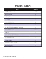
Page 2: ...5 INSTALLATION 6 AC POWER 7 FIXTURE OVERVIEW 8 DMX DATA LINK 9 CONNECTING AND USING DMX DATA LINK 10 FIXTURE OPERATION 10 11 TOKENS 11 FIXTURE MENU STRUCTURE CHART 12 DMX MODES CHARTS 12 MAINTENANCE...

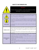
Page 3: ...ERSONAL SAFETY Avoid direct eye exposure to the light source while the product is on Always disconnect this product from its power source before servicing Always connect this product to a grounded cir...

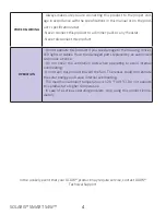
Page 4: ...enses LED lights or cables Have the damaged parts replaced by an authorized technician at once Do not cover the ventilation slots when operating to avoid internal overheating Do not aim this product t...

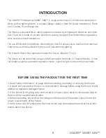
Page 5: ...his fixture Ideal for TV use The fixture can be controlled using any DMX compliant controller 3 Channel Mode 2 chan nel mode as well as automatic operation mode sound to light mode and manual mode BEF...

Page 6: ...MOUNTING THE FIXTURE ON A TRUSS The fixture can be clamped to a truss or similar rigging structure in any orientation When installing the fixture hanging vertically down you can use an open type clam...

Page 7: ...al installation if you want to install it permanently or a power plug not supplied that is suitable for the local power out lets can be installed on the power cable If you replace power plug on the po...

Page 8: ...ink Input and Output XLR Connectors 4 Digital Screen for accessing menu with 4 buttons for navigation Menu Up Down and Enter 5 Aluminum body with fan and Heat sink UP Press UP to change current value...

Page 9: ...rol of a fixture is required it must have its own DMX channels Fixtures that are required to behave identically can share the same DMX address and channels To add more fixtures or groups of fixtures w...

Page 10: ...rom 001 you can change the unit s DMX address according to your lighting setup Optional DMX address values are 1 to 512 When you reach the desired value press ENTER to save your changes STANDALONE MOD...

Page 11: ...ing Solaris fixtures The TOKENS are located above the digital screen on the back panel of the fixture This token indicates the maximum amount of power consumption Displays in Watts This token indicate...

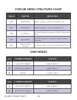
Page 12: ...00 255 C001 Warm White Up Down Buttons change Warm White intensity 000 255 F001 Manual Strobe Function Up Down Buttons Increases Strobe Speed 001 255 FIXTURE MENU STRUCTURE CHART DMX MODES CHANNEL 3 C...

Page 13: ...utdoor events for example If one or more of these factors is present inspect fixtures within their first 100 hours of oper ation to see whether cleaning is necessary Check again at frequent intervals...

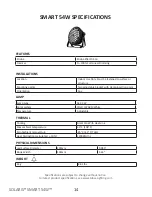
Page 14: ...djustable bracket with clamp insertion point Orientation Any PHYSICAL DIMENSIONS LAMP Lamp type 54 X 3W Color system COLD WARM White Temperature Adjustable FEATURES Strobe Strobe Effect 01 16 Dimmer 0...

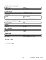
Page 15: ...Input 1 Output ELECTRICAL AC Power 110 230V 50 60Hz Fuse T5A Power Supply Auto Ranging Electronic Switch Mode CONTROL AND PROGRAMMING Control System DMX512 Settings Addressing USITT DMX512 1990 CONST...

Page 16: ...ANY OTHER LOSS OCCASIONED BY THE USE OF INABILITY TO USE OR RELIANCE ON THE INFORMATION CONTAINED IN THIS MANUAL THE GLOW LOGO THE SOLARIS LOGO THE GLOW PROFESSIONAL NAME THE SOLARIS PROFESSIONAL NAME...

Reviews: