SOLARFOCUS octoplus Installation Manual Download Page 6

Technical requirements 

Installation manual 

octo

plus


Provide each boiler with its own chimney 

-  The boiler and the chimney must be coordinated. 

This is the only way to ensure the proper function-
ing of the heating system and the correct dis-
charge of the flue gases. 

-  If there is only one chimney available for two boil-

ers, there is a risk (considering the different oper-
ating states of the boilers - full load/partial load) of 
poor coordination. This can lead to problems (e.g. 
the flue gas has too little energy during the as-
cent, and does not lift off sufficiently from the 
chimney mouth, ...odour pollution by flue gases). 

-  Chimneys with just one device are more reliable 

and safer than chimneys with multiple devices. 

Do not connect a gas boiler and blower boiler to 
the same chimney 

Do not connect a wood-burning stove and 
blower boiler to the same chimney 

-  A wood-burning stove typically requires a larger 

chimney diameter than the blower boiler. 

-  Acoustic disturbance from the blower boiler may 

be possible in the living room (by the wood-burn-
ing stove). 

-  Unnecessary risk due to gas leakage, e.g. if the 

blower boiler is defective. 

Execution of the flue gas pipe 


Run the flue gas pipe towards the chimney in 
a short and rising direction, with as few 
changes of direction as possible. 

-  Change direction in the form of aerodynamically 

favourable arcs, do not build kinks. 

-  The diameter of the flue gas pipe to the chimney 

may be enlarged if required, but may not be re-
duced. 

-  Place the inlet of the flue gas pipe in the chimney 

just below the ceiling. 

-  The flue gas pipe must be tight. Seal seal-less 

flue gas pipes on site with heat-resistant silicone. 

Insulate flue gas pipe 

-  Insulate the flue gas pipe continuously from the 

boiler to the chimney. 

-  Recommended insulation thickness: 50 mm rock-

wool. 

-  Serves to prevent temperature loss and prevents 

the consequential formation of condensation. 

Cleaning opening in the flue gas pipe 

-  To clean the flue gas pipe (e.g. removal of accu-

mulated flue ash) there must be an easily accessi-
ble cleaning opening. 

-  Recommendation: Coordinate the number and 

placement of the cleaning openings with the chim-
ney sweep. 

Opening for emissions measurement in the flue 
gas pipe 

Make an opening (hole) in the flue gas pipe to per-
form the prescribed emission measurement 

 34


Minimum draught requirement for boiler: 5 Pa 

A draught stabiliser must be fitted if the specified 
draught of 15 Pa is exceeded. 

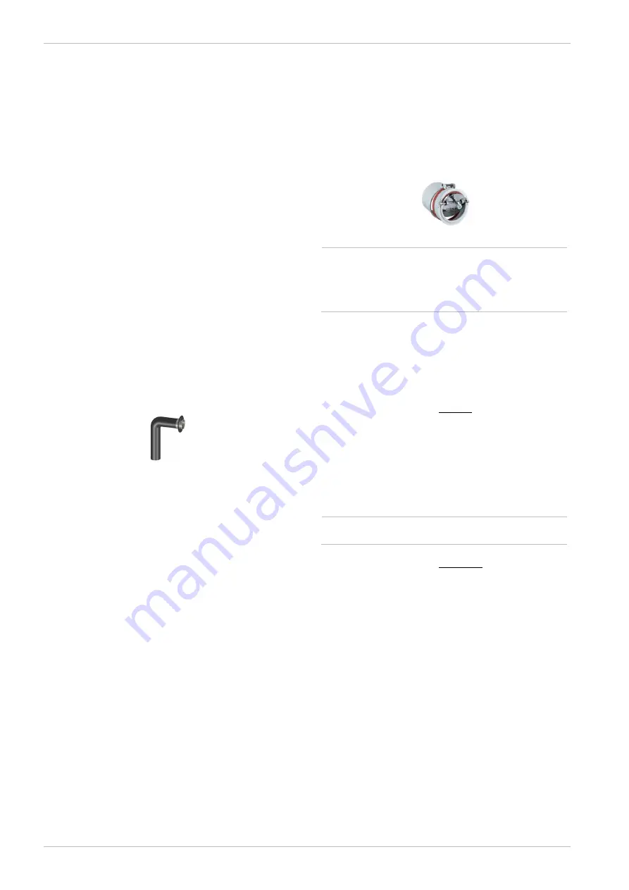
Install explosion flap 


Fig. 2-1: Explosion flap integrated into draught stabiliser 


Before longer horizontal pipe sections 
(L>20xD) and at the high point before drop-
ping down the flue gas pipe, an explosion flap 
must be installed, independent of the boiler 
output. 


In the case of boiler output <50 kW, no explosion 
flap is required (in the case of a short and rising flue 
gas pipe to the chimney). 

3.5  Supply air in the installation room 

 
The following applies for Austria (in accordance with 
H 5170): 
-  For the supply air, 2 cm² per kW thermal output of 

the fuel, but allow at least 200 cm² free cross-sec-
tion. (Thermal output of fuel = boiler output / effi-
ciency) For the exhaust air, allow at least 180 cm² 
free cross-section up to 100 kW nominal heat and 
an additional 1 cm² free cross-section for every 
further kW. 


Calculate at least a further 20% for wire mesh 
in the aeration cross-section. 

 
The following applies for Germany (according to 
specimen firing ordinance): 
-  For heating appliances with a nominal output of 

up to 35 kW, a combustion air opening of at least 
150 cm² or 2 x 75 cm² routed directly into the 
open air must be provided. 

-  Alternatively, a door/window leading outside and a 

room content of at least 4 m³/kW nominal heat 
output are suitable. If the installation room does 
not abut onto an outside wall, combustion air sup-
ply via connecting rooms is possible. Here, the 
combustion air is supplied via a sufficiently dimen-
sioned adjacent room which abuts onto an outside 
wall. 

-  From 35 to 50 kW, provide a free aeration cross-

section of at least 150 cm². From 50 kW upwards, 
for aeration and ventilation, provide a minimum 
free cross-section of 150 cm² for each, plus 2 cm² 
per KW in excess of 50 kW. 

Summary of Contents for octoplus

Page 1: ...l DR 0030 DE Read carefully before operating Pellet boiler octoplus Installation manual for qualified personnel DR 6019 EN v29 202207...

Page 2: ...e boiler power element 37 7 2 Power supply 38 7 3 Connections required for installation 38 7 4 Connecting the control to the internet 38 7 5 Connecting the heating circuit pump X9 X10 38 7 6 Electrica...

Page 3: ...in metal containers Never put hot or warm ash in the dustbin This poses a huge fire risk For repairs use only original spare parts or parts approved by the manufacturer e g standard parts Damage to th...

Page 4: ...in the manufacture of the system that prevent correct and problem free us age We are not liable for parts that were not produced by SOLARFOCUS However we are prepared to transfer our existing claims...

Page 5: ...ing services systems Part 1 Preventing damage from corrosion and scale formation in closed hot water heating systems Austria VDI 2035 Prevention of damage in hot water heating systems Germany SWKI BT...

Page 6: ...removal of accu mulated flue ash there must be an easily accessi ble cleaning opening Recommendation Coordinate the number and placement of the cleaning openings with the chim ney sweep Opening for em...

Page 7: ...two key points must be observed in accordance with Guideline VDI 2035 Avoiding scale buildup limescale Avoiding water side corrosion caused by oxygen in the heating water The lowest possible corrosion...

Page 8: ...trolled modules In addition they allow the use of residual heat If the boiler temperature rises again after the burner has stopped then the charging pump starts the mixer opens and the residual heat f...

Page 9: ...dirt and sludge particles as of 5 m in fully automatic continuous operation from the heating system Ensures the long term correct functioning of heat generators thermostatic valves heat exchangers an...

Page 10: ...gnation 13 3 Adhesive mount cable tie page 28 Fig 5 39 14 6 Loose cable temperature sensor red or with metal shield 15 1 Assembly instructions DR 6019 16 1 Leather glove 17 1 Frame parts kit 18 1 Suct...

Page 11: ...13 13 13 Height to centre of flue gas pipe cm 38 39 39 Flue gas mass flow full load g s 8 4 8 6 11 Flue gas mass flow partial load g s 2 5 2 6 3 8 Maximum flue gas temperature full load 1 C 140 140 14...

Page 12: ...maximum flue gas temperature can be adjusted electronically 2 A draught stabiliser must be fitted if the specified draught of 15 Pa is exceeded attention In the case of a boiler with room sealed oper...

Page 13: ...octoplus 15 octoplus 15 5 22 4 1 4 2 Access to the rear side of the boiler must be provided at least 45 cm on the left or right When the solar pump assembly is fitted onto the octoplus the distance t...

Page 14: ...mm 6 4 mm 4 3 mm exterior diam d2 16 mm 20 mm 15 mm 18 mm 8 mm 5 2 Assemble the boiler Lay all cables temperature sensor motor lambda sensor in such a way that they do not touch the tank raw body wher...

Page 15: ...sert disk shaped insulation 1 under the tank Screw in 4 pcs adjustable feet 2 SW24 and adjust tank level Fig 5 4 Installing the burner Position fire clay brick 1 into the back of the burner unit 2 Mou...

Page 16: ...ig 5 5 Installing the burner cover Bend the tabs 1 in a vertical posi tion on both sides of the burner unit Mount left and right covers 2 in cluding insulation Attach top cover 3 and secure with 4 x s...

Page 17: ...nut 3 Fig 5 7 Mount tank temperature sensor bottom Insert 3 pcs temperature sensors 4 into the bracket and secure with screw DIN7985 VZ M4x10 Lay cables for the sensors on the top of the tank Top tan...

Page 18: ...he tank Fix insulation jacket sections by hooking the plastic strips to the tank Install upper insulation 3 Fig 5 10 Mount cover strips and rosettes Mount 2x cover strips 1 and 8x rosettes 2 on the ta...

Page 19: ...rt must be aligned in plan view to the boiler back panel Fig 5 14 Installing the pellet feeder unit Slide the pellet feeder unit 1 into the intermediate pellet store Connect the two connection spig ot...

Page 20: ...ew the left and right frame part to the retaining plates using hex bolts DIN933 VZ M6x20 and washers DIN9021 6 VZ Use spacer plates 5 as supple mentary shims for vertical orienta tion of the frame if...

Page 21: ...brace 1 with 2 x hex bolts DIN933 VZ M5x12 and washers DIN9021 5 VZ 2 Mount the centre cross brace 3 with 2 x hex bolts DIN933 VZ M5x12 and washers DIN9021 5 VZ 4 Fig 5 20 Connect the intermediate st...

Page 22: ...M3x10 and hex nuts DIN934 VZ M3 4 Fig 5 22 Mount the cable duct Mount the cable duct 1 with 4 x plasterboard dowels 2 Distance from the upper edge of the insulation 40 mm Fig 5 23 Seal condensate drai...

Page 23: ...to X24 Connect lambda sensor 2 to X45 Connect ID fan 3 to X19 and X47 Place temperature sensor 4 in the flue gas pipe connect to X34 Fig 5 25 Mount cable duct cover Lay connector cable for 230 volt AC...

Page 24: ...x nuts DIN934 VZ M8 and washers DIN125A 8 VZ 2 to the threaded bolts Fig 5 27 Flue chambers Mount lower cover Mount lower flue chamber cover 1 with the lower 4 x screws DIN7985 VZ M5x10 and washers DI...

Page 25: ...VZ 3 Fig 5 30 Mount overtemperature reset but ton Screw switching unit 1 behind the cover from the front onto the hex nut and cover cap 2 Connect overtemperature reset button to X20 attach protective...

Page 26: ...2 Fig 5 33 Connect holding magnets Connect primary air holding mag net 1 via the terminal strip 3 at X26 Connect ignition holding magnet 2 to the terminal strip at X27 Fig 5 34 Position temperature s...

Page 27: ...48 Fig 5 36 Mount door Mount door with 2 hinges 1 using 4 x screws M6x30 2 Mount counterpart 3 for magnetic latch with 2 x DIN 965 M4x10 screws 4 to the door Fig 5 37 Mount touch display in door Screw...

Page 28: ...own wire CAN B blue wire Mount rear cover 1 of the display with 4 x self tapping screws M4x10 2 Optional Connect the boiler control to the Internet 38 Ethernet con nectionX2 Fig 5 39 Attach strain rel...

Page 29: ...boiler Connect 2 x pellet hoses 1 using the hinged hose clamps 2 3 return air 4 suction pellets Observe note on installing hoses Fehler Textmarke nicht definiert Connect suction turbine to X3 Connect...

Page 30: ...ne housing Mount housing 1 with 3 x self tap ping screws M4x10 2 to the frame Fig 5 45 Mount front suction turbine cover Mount cover 1 with 4 x self tap ping screws M4x10 2 Fig 5 46 Fix the cable in p...

Page 31: ...tial equalisation Establish connection of flat con nector 1 to power element mount ing screw 2 For screw 2 screw in further Protective conductor cable green yellow of the display Connection to potenti...

Page 32: ...ct flue gas pipe Insert flue gas pipe 1 onto the boiler side connection pipe 2 Flue gas pipe parts and connec tion materials are not included Fig 5 52 Connect boiler hydraulically Connection assignmen...

Page 33: ...deliv ery 5 3 Mounting the room sealed connection Fig 5 54 Mount connection pipe Mount hoses and hose clamps to the feeder unit 1 and air chamber 2 Mount the metal pipe console 3 by means of 2 pcs hex...

Page 34: ...nnection as far as the stop The hose will slide on to the connection pipe better if you apply a little water to the pipe Tighten hose clamps firmly Detachment of the hose and the intake of false air m...

Page 35: ...Flue gas pipe vertical Fig 5 56 6 Hydraulic connection 6 1 Connections overview Fig 6 1_057 HVL FWM Hot water supply fresh water module IT 1 HVL Hot water supply IT 1 FKVL External boiler supply IT 1...

Page 36: ...e factory fitted sealing caps plastic fitted to the solar flow solar re turn connections Failure to comply with this poses a risk of corrosion damage 6 6 2 Circulation pump for optimum tank usage in t...

Page 37: ...X42 Outside temperature sensor Boiler X4 Automatic ignition X16 Automatic ash extraction X19 ID fan X20 Overtemperature reset OTR X23 Feed motor X24 Motors for heat exchanger cleaning X26 Primary air...

Page 38: ...to a network router via cable The connection is required in order to use the following functions mySOLARFOCUS app Weatherman function IP VNC remote access to the boiler control Sending e mails 7 5 Con...

Page 39: ...0 Collector sensor black Silicone cable 2 m PT1000 1620 PT Collector sensor 2 cm x 1 5 Contact sen sor black PVC cable 2 m KTY81 110 69098 Flow sensor to be provided on site KTY81 110 69096 Outside te...

Page 40: ...Initial commissioning 40 Installation manual octoplus 8 1 Commissioning log...

Page 41: ...Initial commissioning Installation manual octoplus 41...

Page 42: ...Initial commissioning 42 Installation manual octoplus 8 2 Customer service order form...

Page 43: ...System schematic Installation manual octoplus 43 9 System schematic 9 1 octoplus with DHW tank and solar system 9 2 octoplus with fresh water module and solar system...

Page 44: ...System schematic 44 Installation manual octoplus 9 3 octoplus with biomass boiler buffer tank DHW tank solar system 9 4 octoplus with biomass boiler buffer tank fresh water module solar system...

Page 45: ...System schematic Installation manual octoplus 45...

Page 46: ...System schematic 46 Installation manual octoplus...

Page 47: ...System schematic Installation manual octoplus 47...

Page 48: ...vironment and your wallet Everything from a single source Products for Pellets Log wood pellets Log wood Wood chips Solar energy Fresh water Heat pump makes you independent Biomass heating Solar energ...

Reviews: