SolarEdge SMI-35-3C-01 Installation Manual Download Page 44

Chapter 7: Setting Up Communication  


Safety and Monitoring Interface Installation Manual – MAN-01-00067-2.1  

43 

43 

2


Select 

Communication


Server


RS485-X Conf

 (X=1 or 2 depending on the specific physical port 

connection) to communicate with different external devices (SolarEdge inverters, revenue meters, 
non-SolarEdge loggers or non-SolarEdge inverters). 

3


To configure the SMI designated as master, select the following in the LCD menus: 


Communication 

 RS485-1 Conf 

 Device Type 


SolarEdge


RS485-1 Conf 

 Protocol 


Master


RS485-1 Conf 


Slave Detect


The system starts automatic detection of the SolarEdge slave SMIs connected to the master SMI. The 
SMI should report the correct number of slaves. If it does not, verify the connections and 
terminations. 

4


Verify the connection of the master to the SolarEdge Monitoring Server, as described in 

Verifying the 

Connection

 on page 44. 

Connecting to Non-SolarEdge Inverters via RS485 

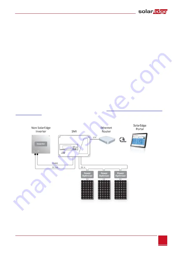
A non-SolarEdge inverter can be connected to the SMI via RS485 for monitoring purposes. The SMI 
extracts information from the non-SolarEdge inverter and transfers it to the SolarEdge monitoring portal. 
Connection to the SolarEdge monitoring portal eliminates the need for an additional monitoring 
connection to the non-SolarEdge inverter, which may be provided by the inverter manufacturer, and 
provides all the monitoring benefits in one place. 

A list of supported inverters is available on SolarEdge website a

http://www.solaredge.com/articles/se-

supported-devices

Do not use the same bus for connecting multiple SMIs and for connecting to a non-SolarEdge inverter. 


Figure 24: Example of SMI Connected to a Non-SolarEdge Inverter 


Summary of Contents for SMI-35-3C-01

Page 1: ......

Page 2: ...discrepancies cannot be excluded No guarantee is made for the completeness of these documents Emission Compliance This equipment has been tested and found to comply with the limits applied by the loc...

Page 3: ...edge it Netherlands 08000221089 support solaredge com United Kingdom 08000281183 Greece 00800125574 Israel 972 73 240 3118 Australia 1800465567 Worldwide 972 73 240 3118 Fax 972 73 240 3117 Before con...

Page 4: ...Package Contents 9 Identifying the SMI 9 Mounting the SMI 9 SMI Connectors 10 Connecting the SMI to AC 11 Chapter 3 Connecting PV Strings to the Safety and Monitoring Interface 13 Overview 13 Chapter...

Page 5: ...g an Ethernet LAN Connection 35 Overview 35 Ethernet Communication Configuration Options 35 Connecting and Configuring LAN 36 Interfacing with Other Devices Using an RS485 Bus 39 Overview 39 RS485 Con...

Page 6: ...nformation about the current subject IMPORTANT SAFETY FEATURE Denotes information about safety issues Instructions WARNING Do not remove the SMI cover before five minutes have elapsed after disconnect...

Page 7: ...is installed between the SolarEdge power optimizers and a non SolarEdge inverter The SMI is compatible with any on grid inverter For some inverters it may also serve as the inverter data logger which...

Page 8: ...ding components to an existing site Refer to the SolarEdge Installation Guide http www solaredge com groups support d ownloads Page 9 Page 13 Page 16 As described in its manual Page 33 Step 1 Step 2 S...

Page 9: ...for P25 screws watchmaker s screwdriver Screwdriver for metal lock nut Electrical screwdriver tester Drilling machine and bits suitable for the surface on which the SMI will be installed Suitable scre...

Page 10: ...ckage Contents One SMI device One mounting bracket Four flat head screws and eight washers for fastening the SMI to the mounting bracket One AC cable connector with a sealing assembly cap One universa...

Page 11: ...e 4 SolarEdge SMI Connectors ON OFF Switch Turning this switch ON 1 starts the operation of the power optimizers Turning it OFF 0 reduces the power optimizer voltage to a low safety voltage LCD Light...

Page 12: ...nector 1 Use the sealing cap to unscrew the locking ring of the AC connector and remove the socket insert Figure 5 AC Connector and Sealing Cap 2 Strip off the AC cable insulation and expose three wir...

Page 13: ...is correctly positioned in the D shaped opening of the main body 7 Screw the locking ring into place To connect the SMI to AC 1 Turn OFF the AC circuit breaker if applicable connected to the SMI 2 Tur...

Page 14: ...Chapter 3 Connecting PV Strings to the Safety and Monitoring Interface Overview The following procedure describes how to connect the DC cables from the power optimizer strings to the SMI The followin...

Page 15: ...er grounding locations marked and NOTE When connecting the SMI to a grounded array the grounding must not be between the SMI and optimizers All grounding should be at the inverter or between the SMI o...

Page 16: ...low The rated maximum input current of the inverter The rated maximum input current of the SMI To connect DC strings to the SMI Connect the DC strings from the photovoltaic strings of optimizers to th...

Page 17: ...llow This LED blinks when monitoring information is received from a power optimizer Fault Red Indicates that there is an error Refer to Appendix A Errors and Troubleshooting on page 46 for more inform...

Page 18: ...ion and accepts a value change with a long press until Applied is displayed Use the three rightmost buttons for entering 123 when entering the password The LCD panel and buttons may be used during the...

Page 19: ...O N O T D I S C O N N E C T V D C 7 2 0 This message is displayed until the DC voltage is safe 50V Do not open the cover until the voltage is safe or until at least five minutes have passed WARNING Do...

Page 20: ...S l a v e D e t e c t Display L C D O n T i m e 3 0 T L M O n T i m e 1 5 Maintenance D a t e a n d T i m e R e s e t C o u n t e r s F a c t o r y R e s e t S W U p g r a d e S D C a r d Information...

Page 21: ...hese menus to move up one menu level or to exit the Setup mode from the main menu The following shows a hierarchical tree of the menu options that appear when using the LCD light button O p t i m i z...

Page 22: ...dge Monitoring Server and the communication option used to communicate between multiple inverters 2 Select Server to set which communication method is used to communicate between the SMI and the Solar...

Page 23: ...S e t M a s k S e t G a t e w a y S e t D N S S e t S e r v e r A d d r S e t S e r v e r P o r t RS485 1 Conf D e v i c e T y p e S E P r o t o c o l M D e v i c e I D 1 S l a v e D e t e c t ZigBee...

Page 24: ...Set the internal real time clock If connected to the SolarEdge monitoring portal the date and time are set automatically and only time zone should be set Reset Counters Reset the accumulated energy c...

Page 25: ...f XXX and YYY are not equal there may be a pairing issue S_OK The connection to the SolarEdge Monitoring server is successful should appear only if the SMI is connected to the server ON OFF Indicates...

Page 26: ...edia Access Control of the IMS I P 1 9 2 1 6 8 2 1 1 9 M S K 2 5 5 2 5 5 2 5 5 0 G W 1 9 2 1 6 8 2 1 M A C 0 2 7 0 2 0 0 3 9 3 6 ZigBee Status This window describes the ZigBee configuration P A N X X...

Page 27: ...o M SolarEdge master o P2P ZigBee point to point o MPM ZigBee multipoint master for a ZigBee coordinator module o MPS ZigBee multipoint slave for a ZigBee router module For a revenue meter reader ref...

Page 28: ...r optimizers and at least one power optimizer is sending monitoring data If P_OK does not appear check the power optimizer string and DC input connections 000 000 Appears only upon first telemetry rec...

Page 29: ...or about 10 seconds The following message is displayed K e e p h o l d i n g b u t t o n f o r p a i r i n g r e l e a s e t o e n t e r m e n u R e m a i n i n g 3 s e c Keep holding for 5 seconds un...

Page 30: ...serial on the SMI label This information is used in the SolarEdge monitoring portal to identify this SMI and is needed to open a new site in the monitoring portal Step 4 Reporting and Monitoring Inst...

Page 31: ...n Refer to Chapter 7 Setting Up Communication on page 33 Providing Installation Information Paper Template Fill out the Physical Layout Template using the detachable 2D barcode stickers on each power...

Page 32: ...age is safe or until at least five minutes have passed 2 Switch the AC to the inverter OFF as described in its manual If applicable turn the inverter AC DC Safety Switch to OFF 3 Verity that the pairi...

Page 33: ...dicator on the LCD panel reads ON P_OK XXX YYY There is a connection to the power optimizers and at least one power optimizer is sending monitoring data Vdc v specifies the DC input voltage which shou...

Page 34: ...nnection to multiple SolarEdge devices on the same bus in a master slave configuration RS485 type can also be used as an interface to external non SolarEdge devices such as revenue meters and data log...

Page 35: ...ions Each gland has three openings The table below describes the functionality of each opening Unused openings should remain sealed Gland Opening Functionality Cable Size diameter 1 One small RS232 2...

Page 36: ...ure the Ethernet LAN port settings Communication S e r v e r L A N L A N C o n f R S 4 8 5 1 C o n f S R S 4 8 5 2 C o n f Z i g B e e C o n f R S 2 3 2 C o n f LAN Conf I P C o n f i g S e t D H C P...

Page 37: ...rEdge monitoring portal IP address and does not normally need configuration Set Server Port Enables setting the port through which to connect to the SolarEdge monitoring portal This option is predefin...

Page 38: ...Depending on the Ethernet connector type RJ45 or an 8 pin terminal block connect as follows If the SMI has an 8 pin terminal block connector for Ethernet communication Pull the connector out as shown...

Page 39: ...tion board or if using a cable drum connect as follows Insert the cable through gland no 1 Remove the cable s external insulation using a crimping tool or cable cutter and expose eight wires Insert th...

Page 40: ...SolarEdge devices such as other SMIs or SolarEdge control and communication gateways The SMI can also connect to non SolarEdge devices such as revenue grade meters and non SolarEdge inverter and read...

Page 41: ...purposes None default for RS485 2 Protocol When selecting a SolarEdge device the following protocols appear under the Protocol option Slave default Master When selecting Device Type Inv Reader the De...

Page 42: ...G on the left of the RS485 X block terminal Figure 21 RS485 RS232 Block Terminal 5 Insert the wire ends into the G A and B pins shown above You can use any color wire for each of the A B and G connec...

Page 43: ...gure 23 SMI RS485 Termination Switch NOTE Only the first and last SMI in the chain should be terminated The other SMIs in the chain should have the termination switch OFF To connect to the Server 1 De...

Page 44: ...and terminations 4 Verify the connection of the master to the SolarEdge Monitoring Server as described in Verifying the Connection on page 44 Connecting to Non SolarEdge Inverters via RS485 A non Sola...

Page 45: ...ommunication option enables using a ZigBee connection for one of the following To connect the IMS to the SolarEdge monitoring portal To create a master slave bus of connected IMSs up to 32 The ZigBee...

Page 46: ...on 1 Turn ON the AC to the SMI by turning on the circuit breakers on the main circuit board and turn on the SMI 2 Wait for the SMI to connect to the SolarEdge monitoring server This may take up to two...

Page 47: ...necessary reconnection time and then restarts During this time the LCD displays the Waking Up message and the remaining time to reconnection WARNING All Warnings and Cautions in this manual should be...

Page 48: ...ndicates that the SMI has established a successful connection and communication with the specified server port device LAN RS485 internal ZigBee module or external GSM modem If the status is not OK a t...

Page 49: ...phy link If OK contact your network IT otherwise replace the cable or change it from cross to straight connection 4th G Server Ping Failed The connection to the Internet is not available Ping to goog...

Page 50: ...age 1 000 VDC Maximum Current 35 A AC Input Input Voltage 90 264 VAC 50 60 Hz Maximum Continuous Input Current 300 mA Physical Ratings Ambient Temperature 20 C to 60 C Enclosure Rating IP65 NEMA 4 Pro...

Page 51: ...s Safety and Monitoring Interface Installation Manual MAN 01 00067 2 1 50 Appendix C Mechanical Specifications The following figure shows the mechanical specifications of the SMI in mm inch Figure 25...

Page 52: ...emoval To open the SMI cover 1 Verify that the SMI is OFF 2 Open the SMI cover s four Allen screws using an M6 Allen screwdriver and carefully lift the cover towards you before lowering it Figure 26 O...

Page 53: ......

Reviews: