background image

Chapter 5: LCD 

 Status Screens and Setup Options 


Control and Communication Gateway Installation Guide - MAN-01-00132-1.2 

34 

Communication Ports Status 

                D e v   P r o t   # #  
R S 4 8 5 - 1 < S E   > < S   > < - - >    
R S 4 8 5 - 2 < - - - > < - - > < - - >  
Z i g B e e   < S E > < M P S > < - - >  

This window presents the communication port (RS485-1/2 or ZigBee), and the devices connected to them, 
with details about the number, type, and protocol. 


DEV

: The type of device that was configured to the specific port ( b

ased on the port’s

 functionality), 

as follows: 


SE

: SolarEdge device (default) 


MTR

: Revenue meter reader 


LGR

: Non-SolarEdge logger 


INV

: Non-SolarEdge inverter  reader 


PROT: 

The protocol type to which the port is set: 

For a SolarEdge device: 


S:

 SolarEdge slave 


M

: SolarEdge master 


P2P:

 ZigBee point-to-point 


MPM:

 ZigBee multipoint master (for a ZigBee coordinator module) 


MPS:

 ZigBee multipoint slave (for a ZigBee router module) 

For a non-SolarEdge logger: 


SS:

 SunSpec   

For non-SolarEdge inverter readers and revenue meter reader, refer to 

http://www.solaredge.com/articles/se-supported-devices

.


##

:


The total number of slaves detected on the specific port  

Sensors Status 

This window displays the status of up to three different sensors connected to the gateway. 

S e n s o r s  
V 1 : X X X . X X X   D e g C  
V 2 : X X X . X X X   W / m 2  
I   : D i s a b l e d  


V1

:  Displays the real time reading of the sensor connected to V1 sensor input


V2

:  Displays the real time reading of the sensor connected to V2 sensor input


I:

  Displays the real time reading of the sensor connected to I sensor input  

The reading is displayed according to the relevant sensor that was configured on the specific sensor input: 


Temperature sensor - the degrees reading in Celsius or Fahrenheit 


Irradiance reading - in W/m2 


Wind speed, in m/s. 


Wind direction, in Deg. 


Summary of Contents for SE1000

Page 1: ......

Page 2: ... where necessary However discrepancies cannot be excluded No guarantee is made for the completeness of these documents FCC Compliance This equipment has been tested and found to comply with the limits for a Class B digital device pursuant to part 15 of the FCC Rules These limits are designed to provide reasonable protection against harmful interference in a residential installation This equipment ...

Page 3: ...way 11 Safety 11 Transport and Storage 11 Package Contents 11 Installation Equipment 11 Installation Guidelines 12 Installation Workflow 12 Mounting and Connecting the SolarEdge Gateway 13 Connecting the SolarEdge Gateway to AC 14 Chapter 3 Connecting the SolarEdge Gateway to the SolarEdge Installation 15 Overview 15 Connecting and Configuring the RS485 15 Verifying the Connection 19 Troubleshooti...

Page 4: ...up Menu Options 35 Language 37 Communication 37 Power Control 39 Sensors 39 Display 39 Maintenance 39 Information 40 Chapter 6 Setting Up Monitoring through the Gateway Optional 41 Communication Dataflow 41 Communication Types 41 Creating an Ethernet LAN Connection 42 Overview 42 Ethernet Communication Configuration Options 42 Connecting and Configuring LAN 43 Troubleshooting Ethernet Communicatio...

Page 5: ...e control and communication gateway Chapter 2 Installing the SolarEdge Gateway page 11 describes how to install the SolarEdge gateway Chapter 3 Connecting the SolarEdge Gateway to the SolarEdge Installation page 15 describes how to connect the control and communication gateway to inverters or Safety and Monitoring Interface SMI using the RS485 bus connection Chapter 4 Connecting Environmental Sens...

Page 6: ...support solaredge jp APAC Asia Pacific support asia solaredge com United Kingdom 0800 028 1183 support solaredge uk US Canada 1 877 360 5292 ussupport solaredge com Greece 0080 0125574 support solaredge com Israel 972 73 240 3118 Netherlands 0800 0221089 Worldwide 972 73 240 3118 Fax 972 73 240 3117 Before contacting ensure you have the following information at hand The communication method to the...

Page 7: ... Denotes a hazard It calls attention to a procedure that if not correctly performed or adhered to could result in injury or loss of life Do not proceed beyond a warning note until the indicated conditions are fully understood and met CAUTION Denotes a hazard It calls attention to a procedure that if not correctly performed or adhered to could result in damage or destruction of the instrument Do no...

Page 8: ...ver and optionally to a non SolarEdge logger The control and communication gateway can connect to the following devices1 SolarEdge devices such as inverters and safety and monitoring interfaces SMIs Non SolarEdge inverters for inverter data monitoring on the SolarEdge portal Environmental sensors Revenue grade meters 3rd party external loggers for inverter data monitoring Power reduction control d...

Page 9: ... 2 Example of sensor connection to the SolarEdge gateway Control and Communication Gateway Interfaces Figure 3 Control and Communication Gateway Interfaces Esc Up 1 Down 2 Enter 3 LEDs DC Micro SD Ethernet Sensors Green power Yellow supply Red input LCD Buttons LCD Optional Optional Antenna1 Antenna2 Control RS485 1 SW1 RS485 2 RS232 USB ZigBee SW2 ...

Page 10: ...enable LCD backlight LEDs The front of the SolarEdge gateway has an LCD panel and three LEDs as shown above The gateway has three LED indicators as follows Power OK Green Indicates whether or not the SolarEdge gateway is connected to power Communication Yellow This LED blinks when monitoring information is received from another SolarEdge device in the installation Fault Red Indicates that there is...

Page 11: ...used for the power supply input as described in Connecting the SolarEdge Gateway to AC on page 14 Sensors enables connecting to external environmental sensors refer to Chapter 4 Connecting Environmental Sensors Optional on page 22 Control used for connection to an external power reducer device SW1 SW2 RS485 1 2 termination Micro SD used for field software upgrade ...

Page 12: ... a similar box which can be closed fully Store the SolarEdge gateway in a dry place where ambient temperatures are 40 C 40 F to 60 C 140 F Package Contents Control and communication gateway 100 240VAC to 12VDC 50 Hz 60 Hz power supply with an interchangeable AC plug US EU AU Accessory kit including Three 3 pin terminal blocks One 7 pin terminal block One 6 pin terminal block Installation Equipment...

Page 13: ...2 mm2 1 000m 3 330 ft Ethernet CAT5 6 100m 325 ft Sensor control interface Recommended wire size 20 AWG 0 52 mm2 50m 165 ft The SolarEdge gateway power supply requires a socket outlet with a grid voltage of 100 V 240 V Protect the SolarEdge gateway from dust wet conditions corrosive substances and vapors Installation Workflow The following provides an overview of the workflow for installing and se...

Page 14: ...n and routing 2 Open the clips at the rear of the gateway by pushing the clips outwards Figure 4 Clips in Open position 3 Position the device on the wall with the open clips as shown in Figure 4 Mark points through the holes of the clips and drill holes using a 4mm diameter drill bit 4 Mount the unit using screw anchors and screws use 3 5mm diameter screws 20mm minimum length not provided by Solar...

Page 15: ... clip down to also release the bottom of the clip No screwdrivers or special tools are required 4 The following figure shows the gateway s rear side when mounted on a DIN rail Figure 6 Gateway mounted on a DIN rail Connecting the SolarEdge Gateway to AC For connecting to power use the supplied power supply 1 Insert the power supply DC connector to the SolarEdge gateway see Figure 3 2 Connect the p...

Page 16: ...gateway The following is an example of a master gateway connected to a chain of slave inverters Figure 5 Example of RS485 connection The following sections describe how to connect the RS485 bus and how to configure its components Connecting and Configuring the RS485 The RS485 bus uses a three wire cable connecting the RS485 1 2 terminal blocks on the SolarEdge gateway to the RS485 input of the inv...

Page 17: ... RS485 chain terminate the gateway by switching a termination dipswitch to ON The switches in the SolarEdge gateway are marked SW1 for the RS485 1 port termination and SW2 for the RS485 2 port termination as shown below Figure 8 RS485 connectors and termination switches 4 Open the inverter SMI cover as described in their manual 5 Remove the seal from one of the openings in communication gland 2 of...

Page 18: ...G A and B pins shown above You can use any color wire for each of the A B and G connections as long as the same color wire is used for all A pins the same color for all B pins and the same color for all G pins 9 Connect all B A and G pins in all inverters SMI The following figure illustrates this connection schema the illustration applies to both inverters and SMI Figure 11 Connecting SolarEdge de...

Page 19: ...dge inverters SMI By default all SolarEdge devices are pre configured as slaves Slaves can be further configured using the RS485 x Conf option in the Communication menu One device must be set as the master on the RS485 bus Any one of the SolarEdge devices may be the master control and communication gateway inverter or SMI If you connect the installation to the SolarEdge monitoring portal the devic...

Page 20: ...y the connection of the Master to the SolarEdge monitoring portal as described in Verifying the Connection below Verifying the Connection 1 After connection a message similar to the following appears in the main status screen see also Initial Gateway Status on page 32 R R C R D i a b l e d S e n s o r s D i s a b l e d S e r v e r L A N S _ O K T o t a l o f S l a v e s 2 Verify that S_OK appears ...

Page 21: ...RS485 1 port Revenue Meter Used when connecting to an external revenue grade meter in order to read the meter data and send it to the monitoring portal For a list of supported meters refer to http www solaredge com articles se supported devices Non SE Logger Used when connecting to an external non SolarEdge logger The logger can read SolarEdge inverters data for Non SolarEdge monitoring purposes N...

Page 22: ...to set the SolarEdge gateway device ID MODBUS ID when connecting to an external master device for example a non SolarEdge logger or to set the ID of the external device for example revenue meter Slave Detect Is used to initiate automatic detection of the slave devices connected to this master gateway The number next to the option is the number of devices that have been detected ...

Page 23: ... supports different voltage ranges One sensor with current output I The following environmental sensor types are supported Sensor Type Configurable Range Unit Temperature 99 0 to 99 0 146 20 to 210 20 C F Irradiance 0 to 9999 W m2 Wind velocity 0 to 99 m s Wind direction 0 to 359 degrees Pyranometer 200 to 2000 W m You can view the sensor data in the Status window see Sensors Status on page 34 and...

Page 24: ...on for V1 V2 and ground 3 V2 Voltage sensor input number 2 4 I Current sensor input negative 5 I Current sensor input positive 6 GND Ground common for V1 V2 and ground 7 12V 12VDC output voltage supply to the sensors limited to 800mA Figure 14 Sensor Interface Inputs To connect a voltage sensor Use a 3 wire cable for this connection Recommended wire size is 0 52mm2 20 AWG with maximum length of 50...

Page 25: ... sensor Use a 3 wire cable for this connection Recommended wire size is 0 52 mm2 20 AWG with maximum length of 50m 164 ft 1 Connect a current source sensor to either I or I depending on its operating range For positive current I pin 5 connect to the current output Iout of the sensor I pin 4 connect to ground GND pin 6 connect to the ground connection terminal of the sensor The 12V pin7 can be used...

Page 26: ... tree of the Sensors menu options Sensors V 1 S e n s o r D i s V 2 S e n s o r D i s I S e n s o r D i s Set V1 V2 I Sensor example for V1 sensor S e n s o r E n R a n g e 0 2 V T y p e T w o P o i n t s Range 0 2 V 0 3 0 m V Sensor Type T e m p A m b i e n t T e m p M o d u l e W i n d S p e e d W i n d D i r e c t i o n I r r a d i a n c e G l o b a l I r r a d i a n c e D i r e c t I r r a d i...

Page 27: ...and P1 represent points on the sensor graph to be configured in the gateway The values refer to the measurement signal and the measurement range from the sensor datasheet Refer to the example below Set point Enables entering two measurement signal values voltage current or temperature Configuring the Sensors in the SolarEdge Gateway To enable the sensors in the SolarEdge gateway 1 Press the Enter ...

Page 28: ...r from the following T e m p A m b i e n t T e m p M o d u l e W i n d S p e e d W i n d D i r e c t i o n I r r a d i a n c e G l o b a l I r r a d i a n c e D i r e c t I r r a d i a n c e D i f f I r r a d i a n c e P O A 3 Select Two Points to configure two points on the sensor graph using the measurement signal and measurement range data from the sensor datasheet P 0 0 0 0 0 P 1 1 0 0 0 1 0 0...

Page 29: ...owing graph shows the min and max values and the focused linear area Figure 17 Example of sensor graph If you want to include the full range of the sensor the points for setting are the minimum and maximum values from the sensor datasheet P 0 0 1 0 P 1 1 0 7 0 However if you want to include a partial range set any value for the two points as long as the points are within the SolarEdge gateway sele...

Page 30: ...nt temperature sensor a voltage output sensor measuring the ambient temperature Electrical output 0 10V Module temperature sensor a current output sensor measuring the module surface temperature Electrical output 4 20 mA Solar irradiance sensor a voltage output sensor measuring the solar irradiance Electrical output 0 1 4 VDC An external 24VDC 1A power supply is required for connecting the tempera...

Page 31: ...ND pins Connect the other ends of the wires to the external power supply and the SolarEdge gateway as follows o UB to V of the power supply o GND to V of the power supply o Out to V2 of the SolarEdge gateway For module temperature sensor Connect the wires to the 2 pin connector Loosen the screws and insert the wire ends into the UB and GND OUT pins Connect the other ends of the wires to the extern...

Page 32: ...sensor connection NOTE When configuring this sensor in the gateway the type should be Irradiance Direct To configure the sensors in the SolarEdge gateway 1 Enter Setup mode as described in in Setup Menu Options on page 35 2 Under the main menu select Sensors 3 Select the preferred sensor submenu V1 V2 or I and select Enable S e n s o r E N R a n g e 0 2 V T y p e T w o P o i n t s If the CPU versi...

Page 33: ...eway ID Status This window displays the ID of the gateway and the software version I D C P U 0 0 0 2 0 3 3 6 Server Communication Status S e r v e r L A N S _ O K S t a t u s O K x x x x x x x x E R R O R M E S S A G E Server The method of connection to the SolarEdge monitoring portal S_OK The connection to the SolarEdge monitoring portal is successful appears only if the inverter is connected to ...

Page 34: ...R e a d y PAN The ZigBee transceiver pan ID CH The ZigBee transceiver channel RSSI The receive signal strength of the neighboring ZigBee transceiver L low M medium H high and no signal ID The ZigBee transceiver ID ZigBee Ready This field is shown only in devices with ZigBee router transceivers slaves in a multi point MP protocol configuration If a ZigBee transceiver is not physically connected a N...

Page 35: ...a ZigBee coordinator module MPS ZigBee multipoint slave for a ZigBee router module For a non SolarEdge logger SS SunSpec For non SolarEdge inverter readers and revenue meter reader refer to http www solaredge com articles se supported devices The total number of slaves detected on the specific port Sensors Status This window displays the status of up to three different sensors connected to the gat...

Page 36: ...Enter button until the following message is displayed P l e a s e e n t e r P a s s w o r d The gateway is now in Setup mode and all its LEDs are lit The gateway automatically exits Setup mode if no buttons are pressed for more than 2 minutes 3 Use the three right most LCD buttons to type in the following password 12312312 The following message is displayed L a n g u a g e e n g C o m m u n i c a ...

Page 37: ...s h F r e n c h I t a l i a n Communication S e r v e r L A N L A N C o n f R S 4 8 5 1 C o n f S R S 4 8 5 2 C o n f Z i g B e e C o n f W i F i C o n f R S 2 3 2 C o n f Power Control R R C R C o n f D i s L o a d D e f a u l t s Sensors V 1 S E N S O R D i s V 2 S E N S O R D i s I S E N S O R D i s Display L C D O n T i m e 3 0 Maintenance D a t e a n d T i m e F a c t o r y R e s e t S W U p ...

Page 38: ...The communication option used to communicate between multiple SolarEdge devices or other external non SolarEdge devices such as revenue meters or loggers 2 Set the communication options as described in Chapter 6 Setting Up Monitoring through the Gateway on page 41 The following shows a hierarchical tree of the menu options in the Communication menu For detailed information of commonly used the con...

Page 39: ... n S e t I P S e t M a s k S e t G a t e w a y S e t D N S S e t S e r v e r A d d r S e t S e r v e r P o r t RS485 1 2 Conf D e v i c e T y p e S E P r o t o c o l S D e v i c e I D 1 ZigBee Conf enabled only if the internal module is connected D e v i c e T y p e S E P r o t o c o l M P M D e v i c e I D 1 P A N I D S c a n C h a n n e l L o a d Z B D e f a u l t s S l a v e D e t e c t 0 Wi Fi...

Page 40: ...e analog sensors V1 V2 Voltage sensors I Current sensors For detailed information about all the configuration options for sensors refer to Chapter 4 Connecting Environmental Sensors Optional on page 22 Display Select Display to set the following L C D O n T i m e 3 0 LCD On Time 30 The number of seconds that the LCD backlight is ON after the LCD button is pressed Maintenance Select Maintenance to ...

Page 41: ...V e r s i o n s E r r o r L o g W a r n i n g l o g Versions Displays inverter firmware versions I D C P U 0 0 0 2 0 3 3 6 0 0 0 0 ID The SolarEdge gateway ID 10 last digits of the S N CPU The communication board firmware version NOTE Please have these numbers ready when you contact SolarEdge support Error Log Displays the last five errors Warning Log Displays the last five warnings ...

Page 42: ...n from the inverter to the SolarEdge monitoring portal through the SolarEdge gateway Ethernet Used for a LAN connection RS485 Enables connection of external devices such as other SolarEdge inverters loggers or a revenue gauge meter and transferring their information through the SolarEdge gateway to the SolarEdge monitoring portal using Ethernet The SolarEdge gateway has two RS485 physical ports RS...

Page 43: ...g portal Figure 21 Example of Ethernet Connection Ethernet Communication Configuration Options The following is a description of the options to configure the Ethernet LAN port settings Communication S e r v e r L A N L A N C o n f R S 4 8 5 1 C o n f S R S 4 8 5 2 C o n f Z i g B e e C o n f W i F i C o n f R S 2 3 2 C o n f LAN Conf I P C o n f i g S e t D H C P e n S e t I P S e t M a s k S e t ...

Page 44: ...S Set the DNS of the SolarEdge gateway according to the LAN settings Set Server Addr Set the IP address of the SolarEdge monitoring portal This option is predefined in the SolarEdge gateway to specify the SolarEdge monitoring portal IP address and does not normally need configuration Set Server Port Set the port through which to connect to the SolarEdge monitoring portal This option is predefined ...

Page 45: ...ons Refer to the Ethernet Communication Configuration Options on page 42 5 Verify the that the status field in the Server Communication Status window displays S_OK S e r v e r L A N S _ O K S t a t u s O K 6 Exit the Setup mode Troubleshooting Ethernet Communication The Server Communication Status window can be used to identify errors S e r v e r L A N S _ O K S t a t u s O K x x x x x x x x E r r...

Page 46: ...rEdge server address as described on page 33 6th 7th 8th Tcp Connect Failed The connection to the SolarEdge server was not established Communication with the server failed Additional Connection Options Wireless ZigBee Connection This communication option enables using a ZigBee wireless connection for one of the following To wirelessly connect the SolarEdge gateway to other SolarEdge devices up to ...

Page 47: ...Wi Fi Power Reduction Interface 4 control pins 5V GND 50 165 m ft RS232 Interface For local connection RS485 Interface Two separate ports 1000 3330 m ft Supported RS485 Devices SolarEdge Devices Yes Revenue Meters Yes Export Inverter Data Yes Export Data to Non SolarEdge Logger Yes Environmental Operating Temperatures 20 to 60 4 to 140 C F Protection Rating IP20 Indoor Mechanical Mounting Type DIN...

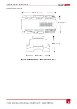
Page 48: ...Specifications Control and Communication Gateway Installation Guide MAN 01 00132 1 2 47 Mechanical specifications Figure 23 SolarEdge Gateway Mechanical Specifications 90mm 3 54 in 161 6mm 6 36 in 90mm 3 54 in 62mm 2 44 in ...

Page 49: ......

Reviews: