background image


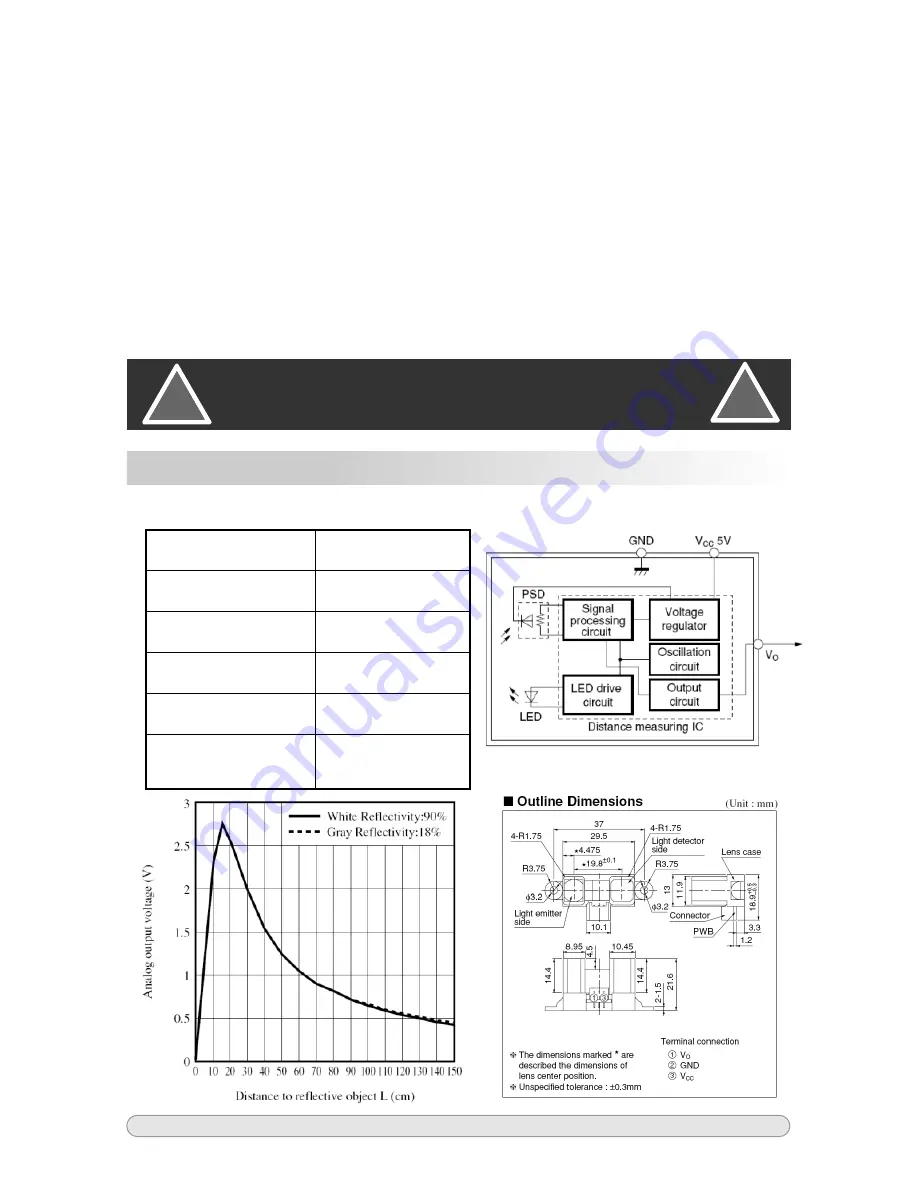
Operating Voltage  4.5~5.5V

Operating Current 33mA

Output Signal  

0.3-2.8 VDC 

Dimension 

4.5x2.2x1.91mm

Detection Angle 

10° 

Detection 
Distance 

20-150 cm 

Block Diagram 

Figure 1 shows object A located at the limit of the PSD’s range (about 15 cm 
away). Notice how that if it were any closer, the light would not hit the  PSD at 
all. Similarly, if B were moved farther away, its’ light would eventually go past 
the ‘top’ of the PSD and would not be seen either (at about 180 cm). This 
explains the limits of the GP2Y.

Think of the PSD as a resistor with a large number of taps (wires coming out at 
various points along the resistor). When light hits the PSD, it hits one of the 
‘taps’  and  causes  current  to  flow  out  each  end  of  the  resistor,  forming  a 
voltage  divider.  As  an  object  moves  closer  or  farther  from  the  sensor, 
incoming light hits a different ‘tap’ causing  the current coming out each end 
of  the  resistor  to  change.  These  currents  are  compared  and  a  voltage 
proportional  to  the  position  of  the  ‘tap’  (and  the  distance  of  the  object)  is 
generated.

Technical Specifications


CAUTION: 

The sensor is a precision device. 

Do Not 

attempt to open the unit. 

Doing so will ruin the delicate alignment of the optics

!

!

www.solarbotics.com

6

AIRRS+ Manual v1.7

Summary of Contents for GP2Y0A02YK0F

Page 1: ...A02YK0F Sensor Analog Infra Red Ranging Sensor The GP2Y0A02YK0F is a well proven robust sensor that uses angle of reflection to measure distances It s not fooled by bright light or different coloured targets Simple to use analog 0 to 2 5V output Small 4 5 x 2 2 x 1 9 cm Connects directly to any microcontroller with A D 20 cm to 150 cm 8 to 79 range ...

Page 2: ...graph at the end of this document but is no wider than 5 cm 2 5 cm either side of centre when measuring at the maximum range Connecting to the AIRRS A custom cable assembly is included with the AIRRS kit The miniature connector is keyed so that it may only be inserted one way The following table shows the necessary connections Table 1 GP2Y0A02YK0F Pinout Pin Symbol Wire Colour Connect To 1 Vcc Red...

Page 3: ...034 15 2 797 2 852 2 840 2 830 20 2 590 2 634 2 606 2 610 25 2 327 2 372 2 350 2 350 30 2 036 2 087 2 067 2 063 35 1 777 1 831 1 810 1 806 40 1 555 1 607 1 587 1 583 45 1 384 1 442 1 406 1 411 50 1 253 1 292 1 274 1 273 55 1 118 1 179 1 164 1 154 60 1 024 1 081 1 047 1 051 65 0 952 1 005 0 971 0 976 70 0 876 0 932 0 902 0 903 75 0 822 0 868 0 847 0 846 80 0 752 0 799 0 789 0 780 85 0 687 0 761 0 7...

Page 4: ... 0 0 5 1 0 1 5 2 0 2 5 3 0 0 20 40 60 80 100 120 140 160 180 200 Distance cm Sensor Output Voltage GP2Y AVG y 57 653x 0 9891 0 0 0 5 1 0 1 5 2 0 2 5 3 0 3 5 4 0 4 5 0 20 40 60 80 100 120 140 160 180 200 Distance cm Sensor Output Voltage GP2Y AVG Power GP2Y AVG www solarbotics com 4 AIRRS Manual v1 7 ...

Page 5: ... controls have shown that even with 2 or 3 remotes pointed at the GP2Y the unit still functions normally Laser Light Tests with a laser pointer had results similar to the flashlight only a beam aimed straight into the sensor s receiver would cause a false reading If the beam comes from even a few degrees off center it has no effect How Does it Work Figure 1 shows how the GP2Y uses an array of phot...

Page 6: ...he PSD as a resistor with a large number of taps wires coming out at various points along the resistor When light hits the PSD it hits one of the taps and causes current to flow out each end of the resistor forming a voltage divider As an object moves closer or farther from the sensor incoming light hits a different tap causing the current coming out each end of the resistor to change These curren...

Page 7: ...b4 invert Remove invert option if using MAX232 or similar When communicating to the Matrix Orbital LCD long value Define variable Long integer Main setup_ADC_ports ALL_Analog Setup all analog pins as only analog setup_ADC ADC_CLOCK_INTERNAL Configure D converter to use internal oscillator set_ADC_CHANNEL 1 Set pin_A1 to measure analog voltage While TRUE delay_ms 500 Pause for 0 5 seconds for LCD t...

Page 8: ...trollers FPGA Development Kits IR Sensors Robotics Kits Part Compilers Instructional Books PIC Programmers Gifts Toys Proto Boards Tools and test equipment Plus Proven and very reliable object sensor Simple 5V Connection Analog signal easily processed by any microcontroller s A2D pin Solarbotics Ltd Calgary Alberta T2E 6M6 Canada 3740D 11A Street NE Suite 101 Toll Free 1 866 276 2687 International...

Reviews: