PRIOR TO INSTALLATION
We recommend using a digital multi meter to test all wires in the vehicle as on-board computer systems can be
damaged by using low resistance testing devices including, test lights, and even computer safe test lights (logic
test probe). Notice Air Bag systems and do not disconnect these systems as it may turn on a “check air bag
system” light or code that may need a dealer scan tool to clear the fault.
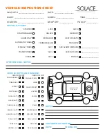
We also recommend testing all functions of the vehicle such as power windows, locks, HVAC systems. Check
for any instrument cluster lights that are on such as “Check Engine”, “Air Bag”, “TPMS” lights. Also check
that all lights work on the vehicle such as brake lights, headlights, interior lights, etc. Also check the interior
and exterior for any damage including scuffs, dents, fingerprints, etc. Be sure to note all deficiencies or other
problems and make customer aware of these before starting the installation.
TESTING VEHICLE WIRES
WHEN LOOKING FOR A POSITIVE (+) WIRE CONNECT ONE LEAD OF YOUR MULTI METER TO A CHASSIS
GROUND.
WHEN LOOKING FOR A NEGATIVE (-) WIRE CONNECT ONE LEAD OF YOUR MULTI METER TO A 12V (+)
CONSTANT SOURCE
12 VOLTS (+) CONSTANT
- You can find different locations for 12V(+) constant. You can use either the (+)
Battery Terminal or the (+) Constant feed to the ignition switch.
To test for this wire use multi meter set to DC Voltage with one lead to chassis ground and the other lead to
probe for a wire that reads between 10-16Volts (+) no matter the position of the key switch. This wire will also
be powering the locks, bypass modules and other circuits so we recommend you DO NOT remove or change
the supplied 30Amp Fuses on the 12V(+) Remote Starter wires. Connect the Red and Red/White wires on CN1
to this wire. If there are 2 12V(+) constant wires at the ignition switch, we recommend connecting the Red wire
from CN1 to one and the Red/White wire from CN1 to the other.
STARTER (+)
- This wire provides a 12V(+) Source to the starter directly or to the starter circuit on the vehicle.
To test for this wire use a multi meter set to DC Voltage with one lead to chassis ground and the other lead to
probe for a wire that reads between 10-16Volts (+) when the key is in the Start (Crank) position in the key switch.
Connect the Purple wire on CN1 to this wire. If there are more than 1 starter wires on the vehicle then you can
use the Pink/White from CN1 and program for 2nd Starter in Menu 2-01 or use the Purple/Black on CN4 through
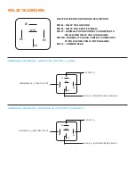
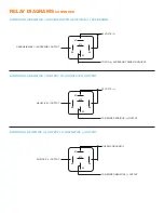
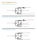
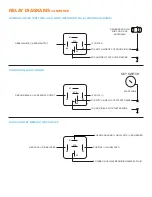
a Relay to power this wire. See relay guide.
STARTER (-)
- This wire provides a Negative(-) Source to the starter circuit on the vehicle.
To test for this wire use a multi meter set to DC Voltage with one lead to 12V(+) Constant and the other lead to
probe for a wire that reads between 10-16Volts (-) when the key is in the Start (Crank) position in the key switch.
Connect the Purple/Black wire on CN4 to this wire.
ACCESSORY (+)
- This wire provides a 12V(+) Source to the HVAC circuits on the vehicle.
To test for this wire use a multi meter set to DC Voltage with one lead to chassis ground and the other lead
to probe for a wire that reads between 10-16Volts (+) when the key is in the ACC and Run position in the key
switch. This wire will NOT show a positive feed in the Start (Crank) position. Connect the Orange wire on CN1
to this wire. If there are more than 1 starter wires on the vehicle then you can use the Pink/White from CN1 and
program for 2nd Accessory in Menu 2-01 or use the Orange/Black on CN4 through a Relay to power this wire.
See relay guide.
ACCESSORY (-)
- This wire provides a Negative(-) Source to the HVAC circuits on the vehicle.
To test for this wire use a multi meter set to DC Voltage with one lead to 12V(+) Constant and the other lead to
probe for a wire that reads between 10-16Volts (-) when the key is in the ACC and Run position in the key switch.
This wire will NOT show a negative feed in the Start (Crank) position. Connect the Orange/Black wire on CN4 to
this wire

