background image

6

SAFETY INSTRUCTIONS

2- SAFETY INSTRUCTIONS


2.1 SAFETY SYMBOLS

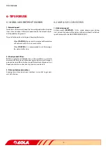
In this operating manual you will find three different symbols rela-

ting to safety:

TO WORK MORE EASILY WITH THE MACHINE.

TO PREVENT DAMAGE TO THE MACHINE AND OPTIO-

NAL EQUIPMENT.

TO PREVENT PHYSICAL INJURY.

On the machine you will find the following warning pictograms:

Read the instructions carefully and observe the safe-

ty advice given in the operating manual.

During the coupling maneuver, stay away from the 

front part of the tractor. Check nobody stands in the 

operational area of the telescopic folding parts.

Risk of serious physical injury.


While maintaining or repairing the planter, stop the 

tractor’s engine and prevent it from starting. The ig-

nition key must be removed.

Risk of being crushed when working under the ma-

chine, please secure the machine to prevent this risk. 

Risk of serious physical injuries.

It is forbidden to ride on the machine during opera-

tion. 

Risk of serious physical injuries caused by 

falling.

Danger of infection from escaping hydraulic fluid at 

high pressure! This can inflict serious injuries with po-

tentially fatal consequences if it passes through the 

skin and into the body. 

Keep the hose lines in good 

condition. Risk of serious physical injuries.

Do not exceed maximum load.

Coupling point for loading and unloading the machi-

ne by crane. See section 2.3 LOADING AND UNLOA-

DING INSTRUCTIONS.

2.2 GENERAL SAFETY REGULATIONS

-  Before starting the machine, please check the ma-

chine is in good condition for work and is safe for 

road use. 

-  Check that visibility is clear around the machine and 

there is no person in the working area.

-  In thoroughfare, please observe traffic signs and re-

gulations.

-  It is forbidden to ride on the machine or climb into 

the machine when it is running. 

-  Before using the machine, the user must be familiar 

with all operating elements.

-  Please be extremely careful when coupling and un-

coupling the machine to the tractor.

Kg. Max.

Summary of Contents for AURA-3215

Page 1: ...WWW SOLAGRUPO COM AURA 3215 Pressurized hopper MAINTENANCE AND DOSAGE STARTING MANUAL ...

Page 2: ...itions The SOLÀ machines are provided with easy to use and efficient devices and perform excellently with only minimum operator maintenance This manual will help you use your SOLÀ product with the maximum efficiency Certified quality system 1st Edition February 2017 Ref CN 811105 GB Created by M A SOLÀ It is forbidden to copy any part of this manual Specifications are subject to change or modifica...

Page 3: ...IREMENTS 10 5 DOSAGE 11 5 1 DISPENSER TYPES 11 5 1 1 ROLLER DISPENSER 11 5 1 2 ENDLESS DISPENSER 12 5 1 3 TRANSFILLING DISPENSER 13 5 2 CALIBRATION TEST 13 5 3 DOSAGE GRAPHS 14 5 3 1 ROLLER DISPENSER 15 5 3 1 1 ROLLER DISPENSER WITH A SINGLE OUTLET 15 5 3 1 2 ROLLER DISPENSER WITH TWO OUTLETS 16 5 3 2 ENDLESS DISPENSER 17 5 3 2 1 ENDLESS DISPENSER WITH A SINGLE OUTLET 17 5 3 2 2 TWO ENDLESS DISPEN...

Page 4: ...4 ...

Page 5: ...vising the machine maintenance inspection and technical assistance and transport For your safety please follow these technical safety instruc tions as SOLÀ will not be responsible for damages caused by not observing the information provided In the first chapters you will find the Technical Characteristics and Safety Instructions Basic concepts that are required to operate the machine are explained...

Page 6: ...juries It is forbidden to ride on the machine during opera tion Risk of serious physical injuries caused by falling Danger of infection from escaping hydraulic fluid at high pressure This can inflict serious injuries with po tentially fatal consequences if it passes through the skin and into the body Keep the hose lines in good condition Risk of serious physical injuries Do not exceed maximum load...

Page 7: ...y when the tractor s engine is off 2 3 USE ACCORDING TO DESIGN The AURA 3215 front hopper has been specifically designed to be used as FRONT DOSING HOPPER for seeds or fertiliser The machine has been designed to work using an agricultural tractor with front lifting unity and three point universal linkage If the machine is used in circumstances other than those specified above the manufacturer will...

Page 8: ...INSTRUCTIONS 3 GENERAL DESCRIPTION 3 1 GENERAL OVERVIEW TRANSPORT PIPES TURBINE DISPENSER CONTROLLER SUPPORT FEET WORK LIGHT BULBS HOPPER PRESSURIZED TRANSPORTATION LIGHTS STEP TO ACCESS HOPPER MANOMETRO COUPLING ACCESSORIES TO REAR MACHINE ...

Page 9: ... name and address 2 Model number of the machine 3 Machine type 4 Serial number 5 CE Certificate and year manufactured to last digits FEATURES VALUES HOPPER CAPACITY 1 350 L Empty weight 320 Kg Maximum Authorized Mass M M A 2 100 Kg Width 2 10 m Length 1 36 m Height 1 62 m Height with optional wheels 1 82 m Dimensions of the filler opening 1 47 m x 0 82 m Category of the hitch Cat II ...

Page 10: ...opper AURA 3215 6 Install and connect the TRANSPORT TUBES from the front hopper up to the specific accessories of the rear duckfoot 7 Lift up the front hopper and put the support feet in a working position IF YOU DON T FOLD THE SUPPORT FEET DURING TRANSPORTATION OR WORK OF THE FRONT HOPPER IT MAY SUFFER DAMAGES DURING THE TRANSPORT OF THE MACHINE CLOSE THE CHOPPER TO PREVENT IT FROM COMPACTING THE...

Page 11: ...LATION CONDITIONS THE DISPENSER SYSTEM IS CAPABLE OF WORKING UP TO 180 Kg Ha WITH AN OUT LET OF Ø80 AND UP TO 250Kg Ha WITH AN OUTLET OF Ø120 WORK WIDTH CONSIDERED IS OF 6 METERS TO PERFORM SEED TRANSFILLING WITH THIS ROLLING DISPENSER YOU MUST CONFIGURE IT WITH 7 SECTORS IN WHICH CASE IT SHALL BE ABLE TO ACHIEVE VALUES CLOSE TO 42 Kg min DEPENDING ON WORK AND INS TALLATION CONDITIONS This dispens...

Page 12: ...E AXLE SMALL AND SIDE SUPPORT BIG PUT THE RINGS BACK TOGETHER CO RRECTLY WHEN ASSEMBLING THE ROLLER LARGE JOINT SMALL JOINT DON T FORGET THE LATCH R OR THE DISPENSER WON T WORK 5 1 2 ENDLESSDISPENSER This dispenser only works for DOSAGE of micro granulated fertilizers in low doses You may switch the endless of this dispenser to adapt it to the desired dose and in order to do that follow the follow...

Page 13: ...ION WORK POSITION 3 Open the calibration cap acting over the 2 closures 4 Put the supplied sack or any other container below the calibration output 5 Act over the PERFORMER or ISOBUS controller of the machine to perform the test see specific PERFORMER or ISOBUS manual 6 Weigh the material in the sack or container and verify that it s the desired dose if not increase or decrease the dose through th...

Page 14: ...MA DOSIFICACIÓN MÁX MÍN 2 SECTOR GRAPH 0 50 100 150 200 250 6 8 10 12 14 DOSIF kg ha VELOCIDAD km h MÁXIMA Y MÍNIMA DOSIFICACIÓN MÁX MÍN 3 SECTOR GRAPH THE AMOUNTS INDICATED WITHIN THE GRAPHS MUST BE CONSIDERED AS ORIENTATION ESTIMA TIONS AS THE PROVIDED FLOW MAY VARY DUE TO THE PRESENCE OF DUST SIZE OF THE PRODUCT TO BE USED DENSITY HUMIDITY ETC BEFORE STARTING TO WORK PERFORM A TEST TO CALIBRATE...

Page 15: ...OSIFICACIÓN MÁX MÍN 0 20 40 60 80 100 6 8 10 12 14 DOSIF kg ha VELOCIDAD km h MÁXIMA Y MÍNIMA DOSIFICACIÓN MÁX MÍN 0 50 100 150 200 6 8 10 12 14 DOSIF kg ha VELOCIDAD km h MÁXIMA Y MÍNIMA DOSIFICACIÓN MÁX MÍN DOSAGE Kg Ha Km h Kg Ha Km h 3 SECTORS 4 SECTORS Kg Ha Km h Kg Ha Km h 1 SECTOR 2 SECTORS 5 3 1 ROLLERDISPENSERWITHASINGLEOUTLET 5 3 1 1 ROLLERDISPENSERWITHASINGLEOUTLET ...

Page 16: ...g ha VELOCIDAD km h MÁXIMA Y MÍNIMA DOSIFICACIÓN MÁX MÍN 0 50 100 150 200 6 8 10 12 14 DOSIF kg ha VELOCIDAD km h MÁXIMA Y MÍNIMA DOSIFICACIÓN MÁX MÍN DOSAGE 5 3 1 2 AROLLERDISPENSERWITHTWOOUTLETS Kg Ha Km h Kg Ha Km h 1 1 SECTORS 2 2 SECTORS ...

Page 17: ... 14 DOSIF kg ha VELOCIDAD km h MÁXIMA Y MÍNIMA DOSIFICACIÓN MÁX MÍN 0 10 20 30 40 50 60 6 8 10 12 14 DOSIF kg ha VELOCIDAD km h MÁXIMA Y MÍNIMA DOSIFICACIÓN MÁX MÍN DOSAGE 5 3 2 ENDLESSDISPENSER 5 3 2 1 ANENDLESSDISPENSERWITHASINGLEOUTLET Kg Ha Km h Kg Ha Km h 1 endless SMALL 38 cm3 1 endless LARGE 75 cm3 5 3 2 2 TWOENDLESSDISPENSERSWITHTWOOUTLETS Kg Ha Km h Kg Ha Km h 2 endless SMALL 2x38 cm3 2 e...

Page 18: ...ng a few meters before stop 2 Check product s flow Perform a previous calibration test in the warehouse in order to know exactly the amount of product going to be spread Dosage is going to be very different when using different kinds of product as it depends on factors such as density moisture content etc 3 Distance between tramlines Keeping the distance between tramlines is essential to get opti ...

Page 19: ...to contact with the eyes or other sensitive parts wash well the affected parts with clean water In case of ingestion contact the medical services immediately 7 1 CHECKING FREQUENCY The periodicity of the check ups indicated below is solely for orien tation purposes It may suffer variations depending on the type of service use of the machine and conditions of use BEFORE STARTING THE SOWING SEASON C...

Page 20: ...c circuit Pneumatic system Clean the dirt from the turbine s protective grille and check its condition Check the condition of the spinning state of the turbine Check the condition of the pipes and replace those that have cracks Rubber components and plastic pieces Check its deterioration and if required replace the damaged components Screws Check the condition of the screws Tighten all screws and ...

Page 21: ... the sowing season see section 3 2 Neither the DEALERSHIP or the BUYER or the USER will be able to claim compensation to MAQUINARIA AGRÍCOLA SOLÀ S L for inci dental damages such as labour costs transport faulty work dama ges to persons or goods harvest loss or reduced harvest etc Material exchanges or returns will be paid by the buyer with the previous consent of MAQUINARIA AGRÍCOLA SOLÀ S L OPTI...

Page 22: ...22 NOTES NOTES DATE NOTES ...

Page 23: ...23 NOTES DATE NOTES ...

Page 24: ......

Reviews: