background image

The Answer in


Power Protection

SOLA 610 UPS Installation

Your UPS is fitted with a DB9 communications
connector on the rear panel. From this connector,
you can access opto coupled outputs indicating
mains failure or low battery.

Alternatively, RS232 serial communications is
available. This RS232 provides a proprietary
command sequence for the computer to monitor the
utility and the UPS status and to control the UPS
output. The data format of the RS232 is 2400bps, 8
bit data, 1 stop bit and no parity.

The battery test mode is also available through the RS232
command sequence whilst the UPS is operating and the
power is normal. During the test, the 4 LED’s (line, bypass,
battery and inverter) will light alternatively until the test is
completed.

Each UPS is supplied with a package of CHECKUPS II®
Advanced UPS communications software. This package
includes the correct interconnection cable for your SOLA 610
UPS. If your computer does not have a DB9 connector on
the serial port, use a standard DB9-DB25 adaptor, available
at most computer accessory stores. The CD-ROM provided
with your UPS includes software for many standard operating
systems and detailed manuals in Adobe Acrobat format. All
utilities required to read and/or print the manuals are included
on the CD-ROM. Refer to section 4.2 & 4.3 for more details
of CheckUPS II® and it’s capabilities.

If you have purchased an AS400® card option, this will be
installed in the communications slot. Be careful to connect
your AS400® interface cable to the correct DB9 connector.
Refer to Section 4.4 for more details of the AS400® card
option.

If you have purchased an SNMP option card, this will be
fitted into the communications slot. Only one (1) card, either
AS40® or SNMP can be fitted into the slot at any one time.
Refer Section 4.5 for more details of the SNMP Card option.

2.9  Setting up the UPS Monitoring from your Computer

DB9

5

1

2

3

4

5

6

7

8

9

RS232 Pin Assignment

GND

RX

1

2

3

4

5

6

7

8

9

Remote
Shutdown
See Note 1

N/O, closes
on Low
Battery

N/C, closes
on Input
Power failure

N/O, closes
on Input
Power failure

TX

Note 1

Remote shutdown when in
battery mode only (i.e. no input
mains power).
Keeping this pin high (+5~+12V)
for 500ms will turn off the UPS
inverter when no input mains
present.

Summary of Contents for 610

Page 1: ...ion Manual Savetheseinstructions This manual contains important instructions that should be followed during installation and maintenance of the UPS Conservercesinstructions Cette notice contient des instructions importantes concernant la securite The Answer in Power Protection Ref 610MANUAL Rev 4 Issued Feb 98 ...

Page 2: ...Howtotalktous If you have any problem a question or require any information on SOLA s extensive range of UPS and power protection equipment this is where to contact us SOLA Australia Ltd 13 Healey Road Dandenong Victoria 3175 Australia Telephone 61 3 9706 5022 Fax 61 3 9794 9150 Service 1800 034 401 Free Call callers outside Melbourne 9768 3105 Melbourne metro callers SOLA Home Page Address www so...

Page 3: ... UPS battery 4 2 8 External Battery connection 4 2 9 Setting up the UPS monitoring from your computer 5 3 UPS Operation 3 1 Switching on the UPS 6 3 2 When the power fails 6 3 3 When the power returns 7 3 4 Front panel indicators 7 4 Optional Features 4 1 Internal Battery Data 8 4 2 External Battery Options 9 4 3 Installing and Operating CheckUPS II 11 4 4 Installation and Operation of the AS400 c...

Page 4: ...Section 5 6 of this manual Should you wish to upgrade the service guarantee to the premier FASTFIX exchange service or extend your warranty beyond the initial two years please contact your local SOLA office We encourage you to read this manual carefully in order to get full benefit from the features built into your SOLA product It is recommended that you register your purchase by completing the wa...

Page 5: ...tion which is protected by copyright All rights are reserved No part of this document may be photographed reproduced or translated to another language without the prior written consent of SOLA This manual contains technical information about the following SOLAUPSsystems iii Rating VA Model No Part No Input Output Voltage Frequency autoselecting Socket type 700 0610 0700A S610 0700 A000 00 240V 50 ...

Page 6: ...ial television and or radio interference The following FCC booklet may be helpful in resolving interference HowtoIdentifyandResolveRadio TVInterferenceProblems StockNumber004 00 00345 4 This booklet is available from the U S Government Printing Office Washington DC 20402 DEPARTMENT OF COMMUNICA T IONS NOTICE This digital apparatus does not exceed the Class A B limits for radio noise emissions from...

Page 7: ...ERSONNEL THERE ARE NO USER SERVICEABLE PARTS INSIDE THE UPS 2 This unit is capable of supplying AC voltage even if there is no input present Although the System On Off Switch on the front of the UPS is protected from accidental actuation be careful the unit does not become unintentionally enabled 3 The SOLA 610 is not authorised for use as a critical component in life support devices without the e...

Page 8: ... PRESENT A RISK OF ELECTRICAL SHOCK AND OR BURN FROM HIGH SHORT CIRCUIT CURRENT OBSERVE PROPER PRECAUTIONS UNE BATTERIE PEUT PRÉSENTER UN RISQUE DE CHOC ÉLECTRIQUE DE BRÛLURE PAR TRANSFER D ÉNERGIE SUIVRE LES PRÉCAUTIONS QUI S IMPOSENT 10 PROPER DISPOSAL OF BATTERIES IS REQUIRED REFER TO YOUR LOCAL CODES FOR DISPOSAL REQUIREMENTS L ÉLIMINATION DES BATTERIES EST RÈGLEMENTÉE CONSULTER LES CODE LOCAU...

Page 9: ...ge to remain within the UPS specifications as detailed for each model Your SOLA 610 is an advanced true on line sine wave UPS with bypass line utilising double conversion technology The utility power enters the UPS where it is rectified to a DC voltage which will float charge the battery as well as run the DC to AC inverter The inverter generates the true sine wave output recreating the utility su...

Page 10: ...hough the packaging for your SOLA 610 was designed specifically for this unit and serves it well in protecting the unit from damage you should unpack the unit immediately and check for signs of concealed damage that may have occurred in transit Concealed damage is damage that may not be apparent by the outside appearance of the packaging In case of damage please notify the delivering carrier at on...

Page 11: ...SPECIFICA T IONS Ambient Operating 1500 m 0o C to 40o C 32o F to 104o F Temperature 1500 3000 m 10o C to 35o C Ambient Storage All Models 15o C to 40o C 5o F to 104o F Humidity All Models 20 to 95 non condensing Altitude All Models 8 000 feet 2500M max To optimise the performance of your UPS we recommend you ensure the battery is fully charged before you use the UPS to support your critical load T...

Page 12: ...does NOT control the delivery of power to the output receptacles All units excluding the 700VA model can be fitted with an external battery option to increase the autonomy when the UPS is operating during a mains failure Refer Section 4 1 for selection of external battery options for your specific UPS On the rear of each of the UPS units 1 3kVA capacity you will find an external battery receptacle...

Page 13: ...able at most computer accessory stores The CD ROM provided with your UPS includes software for many standard operating systems and detailed manuals in Adobe Acrobat format All utilities required to read and or print the manuals are included on the CD ROM Refer to section 4 2 4 3 for more details of CheckUPS II and it s capabilities If you have purchased an AS400 card option this will be installed ...

Page 14: ... from the batteries You may now start the critical equipment that you connected to the UPS If the load level indicator exceeds 100 and the audible alarm sounds twice per second you have plugged too many items into the UPS and overloaded it Remove the non critical items and check the load level indicators When the utility AC source fails the UPS will continue to deliver output to the UPS receptacle...

Page 15: ...unctions during different operating modes of the UPS When utility AC mains is present these will show the equipment load connect as a percentage of the UPS capacity in 25 increments When the UPS is in battery mode these lights will show the amount of battery capacity remaining as a percentage of the full battery capacity in 25 increments This light illuminates when the bypass line is in use and th...

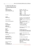
Page 16: ...Voltage 2 4 V 3 6 V 4 8 V 9 6 V 9 6 V Battery Rating 7 0 A H 1 2 V D C 7 0 A H 1 2 V D C 7 0 A H 1 2 V D C 7 0 A H 1 2 V D C 7 0 A H 1 2 V D C No Batteries 2 3 4 8 8 Discharge Time Full Load pf 0 7 6 m i n 6 m i n 5 m i n 1 2 m i n 6 m i n Recharge Time to 90 8 h o u r s m i n i m u m Cut Off Voltage 2 0 V D C 3 0 V D C 4 0 V D C 8 0 V D C 8 0 V D C 4 1 InternalBatteryData ...

Page 17: ...8 28 0610 3BAT 1000 170 80 0610 4BAT 1000 230 110 0610 5BAT 1000 305 150 Battery Packs to suit UPS Model 0610 1500A 1500VA Part Number Runtime with UPS and additional Battery Pack Half Load Full Load 0610 1BAT 1500 35 16 0610 2BAT 1500 60 25 0610 3BAT 1500 150 72 0610 4BAT 1500 210 100 0610 5BAT 1500 270 135 Battery Packs to suit UPS Model 0610 2000A 2000VA Part Number Runtime with UPS and additio...

Page 18: ...The Answer in Power Protection SOLA 610 UPS Optional Features This page intentionally left blank 10 ...

Page 19: ...ll close O Relay contact 2 Summary Alarm Normally open Active will close Active when UPS fails bypass activated Utility input failure and low battery status O Relay contact 3 Remote Shutdown G r o u n d 4 Remote Shutdown Activated by 5 12V for 1 sec duration I 5 C o m m o n Common connection for Pins 1 2 6 7 8 9 R e l a y c o m m o n 6 B y p a s s Normally open Will close when U P S is in Bypass M...

Page 20: ...e communications slot cover plate for reinstallation should the AS400 card option be removed and decommissioned in the future 4 The AS400 card will now be operational when the UPS is turned on and returned to service Output 2 ES 2 Pin connector 4 4 InstallationandOperationofthe AS400 card option cont 12 A plug with link is supplied with the AS400 card option This plug must be installed for normal ...

Page 21: ...ing items One SNMP adaptor card One female male connector cable for connecting the SNMP adaptor card to a PC or terminal for configuration One 3 5 DOS formatted diskette containing the UPS SNMP Agent MIB One 3 5 tar formatted diskette containing the UPS SNMP Agent MIB One User s Configuration and Operations Manual To install the SNMP adaptor card complete the following 1 Shutdown the UPS remove yo...

Page 22: ...r no maintenance Occasionally the input and output connections should be inspected for signs of damage and repaired if necessary If you would like to clean the unit first remove all power to the unit by turning OFF the unit at the System On Off switch and unplugging the unit from the wall outlet or disconnecting the supply at the distribution board for hardwired models If the unit is operating in ...

Page 23: ...bleshooting FuseorCircuit Breaker Troubleshooting Chart Problem Possible Cause Action to Take No Lights No Alarm UPS not ON Rear panel fuse blown or circuit protector tripped Replace fuse or reset protector Restart UPS No incoming utility Check input power No AC Line light alarm beeps every few seconds No incoming utility Check input power Fuse blown or protector tripped Replace fuse or reset prot...

Page 24: ...ess than 4 full linear load Overload Capacity 130 for 1 5 seconds Output Sockets 10 Amp Australian Sockets Efficiency AC to AC Efficiency 80 minimum full load 0 7 pf fully charged batteries Battery Type Sealed Maintenance Free DC Voltage See Internal Battery Data Table page 31 Runtime See Internal Battery Data Table page 31 Bypass UPS to from Bypass Transfer Time Less than 4 milliseconds 2 5 msec ...

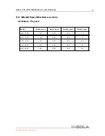
Page 25: ...intenance and Warranty Model Width mm Depth mm Height mm Weight kg 0610 0700 145 405 225 11 5 0610 1000 145 405 225 15 0610 1500 145 465 225 19 5 0610 2000 192 455 350 33 0610 3000 192 455 350 35 5 4 ModelSpecifications cont All Models Physical 17 ...

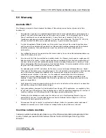
Page 26: ...r s expense For hardwired products 3kVA and above the Warranty covers on site repair Metropolitan area Capital Cities only by Sola technicians or appointed agents For units installed in remote locations Sola Australia may at its discretion request the equipment to be recovered and returned to the factory or other nominated service locations In this case it is the customer s responsibility to pack ...

Page 27: ...e Equipment q Facilities Building wide protection q Other 6 Please specify the equipment being protected by your SOLA UPS Brand Model Operating Sysetm 7 How would you classify your type of business q Retail q Wholesale Distribution q Manufacturing q Telecommunications q Government Education q Banking Finance q Restaurant Hotel q Other 8 What is your company s annual revenue q Less than 1m q 1m 5 m...

Page 28: ...SOLA Australia Ltd 13 Healey Road DANDENONG VIC 3175 AUSTRALIA Affix Postage Stamp ...

Page 29: ...ulting from shipment in a non original container will void this warranty For proper handling upon receipt at SOLA the R A Number must be clearly placed in several locations on the outside of the package SOLA will not be responsible for damage to returned goods that have not been properly packaged or damage exceeding normal wear and tear ForServiceinAustralia contact 1800034401 CallersoutsideMelbou...

Page 30: ...you with many years of service protecting your equipment from surges sags and blackouts This product incorporates the highest quality standards in engineering manufacturing and testing and carries a 2 year warranty against defects in material and workmanship This product is backed by over 60 years of pride and integrity We are sure you will agree there is no substitute for a SOLA SOLA is one of th...

Reviews: