background image

18

Remote Shutdown Via the DB-9 Connector

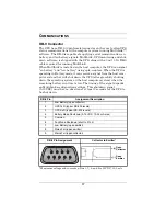
The S2K unit can be shut down remotely by shorting Pins 5 and 6 or 

via Pins 4 and 5 of the DB-9 connector.

Shutdown Via Pins 5 & 6

When Pin 6 is shorted to Pin 5, the UPS output is shut off regardless 

of what mode the UPS is operating in. The UPS cannot be started as 

long as the pins are shorted. When the short is removed, the UPS out-

put can be enabled by pressing the ON/OFF/Alarm Silence button.

Shutdown Via Pins 4 & 5

While the UPS is operating on battery (with no battery test in 

progress), a 5-12VDC signal for 2 seconds or longer is required to sig-

nal a shutdown. Signals for less than 2 seconds are ignored. 
After Pin 4 receives the shutdown signal, a 2-minute shutdown timer 

inside the UPS begins a countdown. The timer cannot be stopped. If 

mains power returns during the 2-minute timer countdown, the shut-

down timer continues until the end of 2 minutes and then the UPS 

turns off.
By default, autorestart is enabled so the UPS will restart after 

10 seconds. If autorestart is disabled via MultiLink software, the UPS 

remains off until a manual restart.

USB Interface Port

The S2K unit has a USB interface port for communication that will 

work with most power management software and provide UPS sta-

tus and management of the automatic orderly shutdown of the com-

puter. The S2K’s USB communications meets HID standard, 

version 1.11

Data Line Protection Connectors

Data line (IN & OUT) connectors are located on the rear of the UPS 

and provide transient voltage surge suppression (TVSS) for Phone/

Fax/DSL/Internet/Modem devices.

Summary of Contents for S2K

Page 1: ...S2K UPS USER MANUAL Line Interactive 350 1000 VA 230V...

Page 2: ......

Page 3: ...INDICATORS 12 ON OFF Alarm Silence Button 12 Status Indicators Mains Battery Fault 13 Mains Indicator Green Amber 13 Battery Indicator Green Amber 13 Fault Indicator Red Green 13 Location and Status...

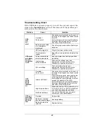
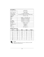
Page 4: ...PS 19 Maintaining Batteries 19 Battery Replacement 19 Battery Replacement Procedure 20 TROUBLESHOOTING 21 Guide to Status Indicators 21 Troubleshooting Chart 22 SPECIFICATIONS 23 Battery Run Times 24...

Page 5: ...and operated by individuals without previous training WARNING SAFETY PRECAUTIONS There are no user serviceable parts inside this UPS except the internal battery pack Refer all UPS service to quali fie...

Page 6: ...erve the following rules Turn off and unplug your UPS before cleaning Do not use liquid or aerosol cleaners A dry cloth is recommended to remove dust from the surface of your UPS Do not install or ope...

Page 7: ...pen or mutilate the battery or batteries Released electrolyte is harmful to skin and eyes It may be toxic When replacing the battery use same number and type of battery as the suitable recommended typ...

Page 8: ...n an ambient temperature range of 0 C to 40 C 32 F to 104 F Install in a clean environment free from conductive contaminates moisture flammable liquids gases or corrosive substances Provided are a Mul...

Page 9: ...ion for PCs point of sale sys tems network and similar electronic equipment It offers a configurable input voltage window allowing you to precisely match your equipment s input power Three communicati...

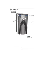
Page 10: ...6 Front View of UPS Power ON OFF Alarm Silence Battery Indicator Green Amber Fault Indicator Red Green Mains Indicator Green Amber For details see Controls and Indicators section...

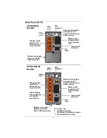
Page 11: ...models 350 500VA Models Input circuit protector Orange output receptacles Battery backup surge protection Black output receptacles 2 Surge protection only Data Line Protection Connectors 2 Phone Fax D...

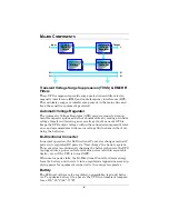
Page 12: ...uations without uti lizing the batteries Bi Directional Converter In normal operation the Bi Directional Converter changes mains AC power into regulated DC power to float charge the battery system Thi...

Page 13: ...ultiLink software CD MultiLink serial cable 3 0m 10 ft USB cable 1 8m 6 ft RJ 11 cord 2 1m 7 ft Two 2 10A output power cords 2 0m 6 6 ft MultiLink serial cable 3 0m 10 ft Sola S2K Unit MultiLink softw...

Page 14: ...l Services 2 Decide where to place the S2K unit Find a location that is near an easily accessible mains outlet Install the UPS indoors in a con trolled environment where it cannot be accidentally turn...

Page 15: ...ment 9 Communication options see Communications section for details Option 1 Serial Communications Serial communications provides parametric data for example input voltage and battery voltage a Connec...

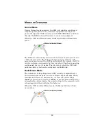
Page 16: ...e pressing the main ON OFF button for more than two 2 seconds will shut down the UPS An audible alarm sounds briefly Alarm Silence When a UPS alarm is active pressing and releasing the main ON OFF but...

Page 17: ...mber denotes Buck Boost mode Battery Indicator Green Amber The Battery Indicator illuminates to indicate the UPS is operating on battery green or to signify a battery warning amber Fault Indicator Red...

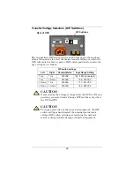
Page 18: ...ns Input Range Setting Up Up 230VAC 163 282VAC default Up Down 220VAC 155 270VAC Down Up 240VAC 171 291VAC Down Down 230VAC 163 282VAC CAUTION Never change the voltage settings while the UPS is ON and...

Page 19: ...tched off By default the UPS is set to perform an automatic battery test after it has been operating continuously for two 2 weeks The interval at which the UPS will perform a battery test can be confi...

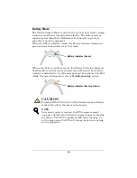
Page 20: ...o flashing amber and the alarm sounds every half second Low battery warning is defaulted to two 2 minutes but can be configured via Mul tiLink For more information refer to Troubleshooting section CAU...

Page 21: ...st com puter system that will shut down the UPS after gracefully shutting down the operating system on the host computer system when the remaining battery run time is low The timing of the signal depe...

Page 22: ...down signal a 2 minute shutdown timer inside the UPS begins a countdown The timer cannot be stopped If mains power returns during the 2 minute timer countdown the shut down timer continues until the e...

Page 23: ...the batteries Battery Replacement This UPS is equipped with internal hot swappable batteries that the user can replace without shutting down the UPS or connected loads CAUTION A battery can present a...

Page 24: ...from the UPS Figure 2 Figure 1 Figure 2 3 Disconnect the insulated con nectors from the battery termi nals Figure 3 4 Insert a new battery pack and push the connectors onto the battery ter minals blac...

Page 25: ...een ON Normal operation with mains power present no beep Green ON UPS is operating on battery beep every 10 seconds Green ON Battery test has been initiated no beep Amber ON UPS is operating in Buck B...

Page 26: ...hreshold Wait until the voltage rises to an appropriate level or have the mains checked by a qualified electrician AC overvoltage Wait until voltage lowers to an appropriate level or have the mains ch...

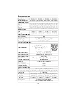
Page 27: ...range Battery backup surge protection 2 IEC 320 C13 black Surge protection 6 IEC 320 C13 orange Battery backup surge protection 2 IEC 320 C13 black Surge protection Output Power Cables 2m 6 6 ft detac...

Page 28: ...ESD EN61000 4 2 Level 3 Criteria A Susceptibility EN61000 4 3 Level 3 Criteria A Electrical Fast Transient Burst EN61000 4 4 Level 3 Criteria A Emissions EN50091 2 Class B Conducted Immunity EN61000...

Page 29: ...m Click on the Warranty link and fill in the form This will register your product with Sola Hevi Duty For UPS purchasers The MultiLink software is available for down load in the Products section of ou...

Page 30: ...26...

Page 31: ......
Page 32: ...se of this information or for any errors or omissions 2003 Sola Hevi Duty All rights reserved throughout the world Specifications subject to change without notice Sola Hevi Duty name and logo are regi...

Reviews: