background image

This is the mark of the Japan Surveying    
Instruments Manufacturers Association.

Summary of Contents for DT20C

Page 1: ...SURVEYING INSTRUMENTS OPERATOR S MANUAL DT7C DT20C Electronic Digital Theodolite ...

Page 2: ...This is the mark of the Japan Surveying Instruments Manufacturers Association ...

Page 3: ...ully Verify that all equipment is included C 12 1 Standard Equipment The specifications and general appearance of the instrument may be altered at any time and may differ from those appearing in brochures and this manual Some of the diagrams appearing in this manual may be simplified for easier understanding SURVEYING INSTRUMENTS OPERATOR S MANUAL ...

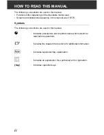
Page 4: ...ring in this manual are of DT7C Symbols The following conventions are used in this manual G Indicates precautions and important items which should be read before operations C Indicates the chapter title to refer to for additional information Indicates supplementary explanation Indicates an explanation for a particular term or operation Key Indicates operation keys ...

Page 5: ...8 2 Set Horizontal Circle to a Required Value Horizon tal angle hold 17 8 3 Changing Horizontal Angle Display Mode 18 8 4 Changing Vertical Angle Display Mode 18 8 5 Stadia Survey 19 9 CHANGING INSTRUMENT OPTIONS 21 10 ERROR MESSAGES 28 11 CHECKS AND ADJUSTMENTS 29 11 1Plate Level 29 11 2Circular Level 30 11 3Reticle 31 11 4Optical Plummet 33 12 STANDARD EQUIPMENT 35 12 1Standard Equipment 35 12 2...

Page 6: ...iv ...

Page 7: ...nual s main text Definition of Indication Definition of Symbols C WARNING Ignoring this indication and making an operation error could possibly result in death or serious injury to the operator C CAUTION Ignoring this indication and making an operation error could possibly result in personal injury or property damage J This symbol indicates items for which caution hazard warnings inclusive is urge...

Page 8: ...nal Accessories E When securing the instrument in the carrying case make sure that all catches including the side catches are closed Failure to do so could result in the instrument falling out while being carried causing injury D Do not use the carrying case as a footstool The case is slippery and unstable so a person could slip and fall off it D Do not place the instrument in a case with a damage...

Page 9: ...mounting the instrument to a tripod tighten the centering screw securely Failure to tighten the screw properly could result in the instrument falling off the tripod causing injury E Tighten securely the leg fixing screws of the tripod on which the instrument is mounted Failure to tighten the screws could result in the tripod collapsing causing injury D Do not carry the tripod with the tripod shoes...

Page 10: ...ity To prevent the keys from becoming stiff remove the connector caps before moving the DT to a cold place Never place the DT directly on the ground Sand or dust may cause damage to the screw holes or the centering screw on the base plate Protect the DT from heavy shocks or vibration Never carry the DT on the tripod to another site Turn the power off before removing the battery When placing the DT...

Page 11: ...tripod for loose fit and loose screws If any trouble is found on the rotatable portion screws or optical parts e g lens contact your local dealer When the instrument is not used for a long time check it at least once every 3 months C 11 CHECKS AND ADJUSTMENTS When removing the DT from the carrying case never pull it out by force The empty carrying case should be closed to protect it from moisture ...

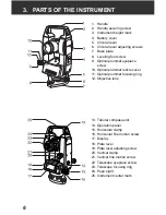
Page 12: ...lummet eyepiece screw 10 Optical plummet reticle cover 11 Optical plummet focusing ring 12 Objective lens 13 Tubular compass slot 14 Operation panel 15 Horizontal clamp 16 Horizontal fine motion screw 17 Display 18 Plate level 19 Plate level adjusting screw 20 Vertical clamp 21 Vertical fine motion screw 22 Telescope eyepiece screw 23 Telescope focusing ring 24 Peep sight 25 Instrument center mark...

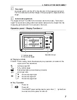
Page 13: ... the measuring point where DT is mounted to this mark Operation panel Display Functions z Display symbols P SAVE Power saving mode Deactivated by key operation or rotation of the upper part of the instrument Vertical angle 90 vertical angle Remaining battery power display 4 levels gon angle units Horizontal angle right Horizontal angle left Horizontal angle hold z Key Operation Power on Power off ...

Page 14: ...FF Hold for a moment Continue holding down the button until the horizontal angle beep has or has not been set The setting can also be changed with the setting screen C 9 CHANGING INSTRUMENT OPTIONS Set horizontal angle to 0 C 8 1 Measuring the horizontal angle between 2 points H angle 0 Hold release horizontal angle C 8 2 Set Horizontal Circle to a Required Value Horizontal angle hold MENU Enter I...

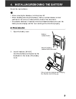
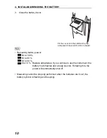
Page 15: ...ent Use alkaline batteries If batteries other than alkaline batteries are used the battery reserve display and the Low warning will not function properly XPROCEDURE 1 Open the battery cover 2 Insert 2 batteries LR14 C Insert the batteries as depicted by the illustration on the inside of the battery cover Press the battery release button downward Battery release button Firmly insert the batteries a...

Page 16: ...l batteries If you continue to use the instrument the battery mark flashes and a beep sounds Following this the power will automatically shut off Measuring cannot be properly performed when the batteries are Low the battery symbol is flashing and beeping Fit the cover into the catch at the top and press it down until a click is heard ...

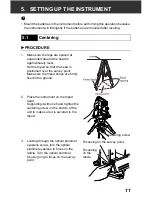
Page 17: ...is positioned over the survey point Make sure the tripod shoes are firmly fixed in the ground 2 Place the instrument on the tripod head Supporting it with one hand tighten the centering screw on the bottom of the unit to make sure it is secured to the tripod 3 Looking through the optical plummet eyepiece screw turn the optical plummet eyepiece to focus on the reticle Turn the optical plummet focus...

Page 18: ...rom the off center direction of the bubble Adjust one more tripod leg to center the bubble Turn the leveling foot screws while checking the circular level until the bubble is centered in the center circle 3 Loosen the horizontal clamp to turn the upper part of the instrument until the plate level is parallel to a line between leveling foot screws A and B Center the air bubble using leveling foot s...

Page 19: ... of the bubble displacement b Turn the upper part a further 90 and use leveling foot screw C to remove half of the displacement in this direction Or adjust the plate level C 11 1 Plate Level 6 Turn the instrument and check to see if the air bubble is in the center position in all directions If it is not repeat the leveling procedure 7 Loosen the centering screw slightly Looking through the optical...

Page 20: ...Tighten both clamps 3 Turn the telescope focusing ring to focus on the target Turn the vertical and horizontal fine motion screws to align the target with the reticle The last adjustment of each fine motion screw should be in the clockwise direction 4 Readjust the focus with the focusing ring until there is no parallax between the target image and the reticle Eliminating parallax This is the relat...

Page 21: ...on a self check is run to make sure the instrument is operating normally If everything is normal the display is ready for measurement The ON OFF power setting may be set so that by itself can be used to turn the power on and off C 9 CHANGING INSTRUMENT OPTIONS ...

Page 22: ...h a single detector By employing methods used in conventional angle measurement with diametrical detection precision equivalent to diametrical detection can now be obtained with a single detector In addition the reduced number of detectors leads to an overall reduction in power consumption of the instrument CIndependent angle calibration cannot be performed by the user Consult your local dealer XP...

Page 23: ...gle hold 1 Turn the upper part of the instrument and display the horizontal angle you want to set 2 Press twice The horizontal angle is now in hold status 3 Sight the direction that you want to set the horizontal angle to in step 2 and press again The horizontal angle hold status is released 8 2 Set Horizontal Circle to a Required Value Horizontal angle hold ...

Page 24: ...is pressed horizontal angle right left is switched XPROCEDURE Selecting vertical angle display mode Angle slope in slope in 1 Set Item No 5 function to Angle slope in in advance C 9 CHANGING INSTRUMENT OPTIONS 2 Change the vertical angle direction on measuring screen Every time is pressed vertical angle display is switched between angle slope in and angle slope in 8 3 Changing Horizontal Angle Dis...

Page 25: ... two horizontal which can be used to measure the target distance and height difference as follows Stadia line separation 1 100 of the focal distance When the telescope is horizontal Horizontal distance between a and b L 100 Height difference between a and b h h1 h2 8 5 Stadia Survey ι Δ ...

Page 26: ...8 MEASUREMENT 20 When the telescope is slanted Horizontal distance between a and b L or L Height difference between a and b h h1 h2 or h h1 h2 100 ι θz sin2 100 ι θv cos2 Δ 50 ι θz sin2 Δ 50 ι θz sin2 ...

Page 27: ...display Item screen 2 Press until the item you want to change is displayed Details of the items are explained in the table above 3 Press until the option you want to select is displayed Details of the items are explained in the table above 4 Press MENU to set the selected option The measuring screen is restored Item NO Options ...

Page 28: ...ng Item NO Parameter Options Display 1 Vertical angle display mode C Vertical angle display method Zenith 0 Horizontal 0 Horizontal 90 3 Auto power cut off The power will automatically shut off 15 minutes after the last operation The power will automatically shut off 30 minutes after the last operation Will not shut off ...

Page 29: ...er will automatically shut off 5 minutes after the last operation The power will automatically shut off 10 minutes after the last operation 5 function Horizontal angle Right left Angle slope in Angle slope in Item NO Parameter Options Display ...

Page 30: ... CHANGING INSTRUMENT OPTIONS 24 6 Minimum display DT7C 10 DT20C 20 DT7C 5 DT20C 10 7 Unit Degree Gon Mil 8 Procedures for turning the power OFF Both methods are possible Item NO Parameter Options Display ...

Page 31: ...isplay options in Item NO 6 will change as shown below to reflect the Unit type selected in Item NO 7 9 Horizontal angle beeps Beeps Does not beep 10 Active mode Off On Degree Gon Mil 5 0 001 0 02 10 0 002 0 05 20 0 005 0 10 Item NO Parameter Options Display ...

Page 32: ...he positions So that horizontal angles can be differentiated rapid and slow beeping alternates in the adjoining positions Even if the position is beeping it will stop 3 seconds after the horizontal angles have not been rotated The beeping sound can be set to beeps does not beep by holding down the as well C 3 PARTS OF THE INSTRUMENT Zenith Vertical Vertical 90 270 0 180 90 1 to 15 vicinity 75 to 8...

Page 33: ...ing itself every 1 5 seconds to 0 5 seconds This is suitable for operations setting out alignment etc whereas the instrument is fixed for a set period of time at a set angle Active Mode ON The display is constantly refreshed about every 0 5 seconds In comparison to Active Mode OFF energy consumption is somewhat higher This is suitable for successive measuring set collection etc XPROCEDURE Displayi...

Page 34: ...isplayed Error messages starting with E indicate trouble with the instrument Contact your local dealer Display messages Meaning _ _ _ Either the vertical circle or the horizontal circle is turned too fast to measure the value After a brief interval the previous display is restored ...

Page 35: ...damaged by a strong shock Make sure the instrument is securely set up and stable before performing checks and adjustments The bubble tube is made of glass so it is sensitive to temperature changes or to shock Check and adjust it as outlined below XPROCEDURE Checking and adjusting 1 Level the instrument and check the position of the bubble in the plate level C 5 2 Leveling steps 3 to 5 2 Turn the u...

Page 36: ... even when the adjustment has been repeated have your local dealer adjust it XPROCEDURE Checking and adjusting 1 Perform the plate level inspection and adjustment C 11 1 Plate Level 2 Check the position of the bubble in the circular level C 5 2 Leveling step 1 to 2 If the bubble is not off center no adjustment is necessary If the bubble is off center perform the following adjustment 3 First confir...

Page 37: ... the reticle to the horizontal axis 1 Carefully level the instrument 2 Align a clearly visible target the edge of a roof for example on point A of the reticle line 3 Use the telescope fine motion screw to align the target to point B on the vertical line If the target moves parallel to the vertical line adjustment is unnecessary If its movement deviates from the vertical line have your local dealer...

Page 38: ... Horizontal angle A1 18 34 00 Vertical angle B1 90 30 20 4 While the telescope is in face right sight the center of the target and read out the horizontal angle A2 and the vertical angle B2 Example Horizontal angle A2 198 34 20 Vertical angle B2 269 30 00 5 Do the calculations A2 A1 and B2 B1 If A2 A1 is within 180 20 and B2 B1 is within 360 40 adjustment is unnecessary Example A2 A1 Horizontal an...

Page 39: ... adjustment XPROCEDURE Adjustment 3 Correct half the deviation with the leveling foot screw 4 Remove the optical plummet reticle cover 5 Use the 4 adjusting screws of the optical plummet to adjust the remaining half of the deviation as shown below When the survey point is on the upper or lower part of the illustration Loosen the upper lower adjusting screw slightly and tighten the lower upper adju...

Page 40: ... the survey point to a point in the center of the optical plummet G Be extremely careful to adjust all the adjustment screws by the same amount so that none will be over tightened 6 Check to make sure that the survey point remains centered on the reticle even if the upper part of the instrument is rotated If necessary perform the adjustment again 7 Replace the optical plummet reticle cover 4 3 3 4...

Page 41: ...pment is included 12 1 Standard Equipment 1 DT main unit 1 2 LR14 C alkaline battery 2 3 Lens cap 1 4 Lens hood 1 5 Plumb bob 1 6 Tool pouch 1 7 Screwdriver 1 8 Lens brush 1 9 Adjusting pin 2 10 Cleaning cloth 1 11 Operator s manual 1 12 Carrying case SC181 1 13 Carrying strap 1 ...

Page 42: ...are sold separately from the DT zTubular compass CP7 Slide the tubular compass into the tubular compass slot loosen the clamp screw then rotate the top part of the instrument until the compass needle bisects the index lines The telescope s face left sighting direction in this position will indicate magnetic north After use tighten the clamp and remove the compass from the slot G The tubular compas...

Page 43: ...hen sighting targets where glare is present solar observations for example attach it to the objective lens of the DT to the eyes of its operator zBattery Unit BDC55 BDC55 is used as the power source for the ACE5 and LAP1 zAuto collimation eyepiece ACE5 The ACE5 is designed to detect a slight shift in inclimation of the reflector The BDC55 is the power source for the ACE5 The buttons on the BDC55 c...

Page 44: ...ower source for the LAP1 The buttons on the BDC55 can also be used to operate the LAP1 For details see the LAP1 Operator s manual The following numbers indicate the equipment listed in 12 1 Standard Equipment 12 3 Layout Plan 4 6 7 8 9 2 CP7 Optional accessory 10 5 1 3 ...

Page 45: ...atures Ni Cd batteries are recommended G If batteries other than alkaline batteries are used the battery reserve display and the Low warning will not function properly Electrical discharge of alkaline batteries Active Mode OFF default setting 13 1 Battery Selection 65 130 65 130 Duration H Duration H Voltage V Voltage V ...

Page 46: ...ibration System with Single Detection Provided Minimum display DT7C 5 0 001gon 0 02 mil 10 0 002 gon 0 05 mil DT20C 10 0 002 gon 0 05 mil 20 0 005 gon 0 1 mil Selectable with parameter Accuracy DT7C 7 DT20C 20 ISO 17123 3 2001 Measuring time Active Mode ON Every 0 5 sec Active Mode OFF Non operation Every 1 5 sec Operation Less than 0 5 sec Measuring mode Horizontal angle Right Left Selectable wit...

Page 47: ...nt powers off if not used for 5 min 10 min 15 min 30 min Off selectable with parameter Sensitivity of levels Plate level 60 2 mm Circular level 10 2 mm Optical plummet Image Erect Magnification 3X Minimum focus 0 3 m from base plate Operating temperature 20 to 50 C Storage temperature 30 to 70 C Dust and water resistance IP66 IEC 60529 2001 Instrument height 236 mm Size 165 W X 165 D X 341 H mm wi...

Page 48: ...operated in a commercial environment This equipment generates uses and can radiate radio frequency energy and if not installed and used in accordance with the instruction manual may cause harmful interference to radio communications Operation of this equipment in a residential area is likely to cause harmful interference in which case the user will be required to correct the interference at his ow...

Page 49: ......

Page 50: ...3rd ed 03 0809 Printed in China 2007 SOKKIA TOPCON CO LTD ...

Reviews: