


28
Axis
3™
Chapter 4
Axis
3
Operation
4.2
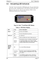
Interpreting LED Indicators
The Axis
3
receiver has three LED indicators. You can determine
operation status including power, DGPS lock, GPS lock and L-
Band presence by the color of each indicator. Refer to the
following table for more information.
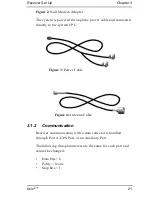
Figure 2: Axis
3
Front Panel LED Display
Table 2: LED Status Display
LED
Color
Status Description
Power
Off
Power not connected
Red
Power connected to the receiver
GPS Lock
Off
No GPS lock
Yellow
GPS lock (about one minute after power on)
Blinking
Yellow
Differential processor verification will blink three
to four times at power up. If it does not blink,
possible differential processor failure. Repeated
blinking indicates GPS processor failure
L-Band/
Beacon/
WAAS
Lock
Off
No L-band differential signal
Flickering
Yellow
Receiver is close to acquiring L-band/WAAS
differential signal (not applicable when in Bea-
con mode)
Blinking
Yellow
L-band/WAAS signal acquired, but signal is
weak (not applicable when in Beacon mode)
Summary of Contents for Axis 3
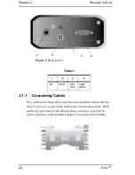
Page 1: ... Axis 3 TM Operations Manual Part Number 750 1 0060 Rev 2 GPS Receiver System ...
Page 6: ......
Page 10: ......
Page 11: ...Welcome Chapter 1 Axis 3 5 ...
Page 33: ......
Page 41: ......
Page 43: ......
Page 48: ......
Page 51: ...43 Axis 3 Appendix C Frequently Asked Questions ...
Page 53: ......


