background image


8. Component Specifications 

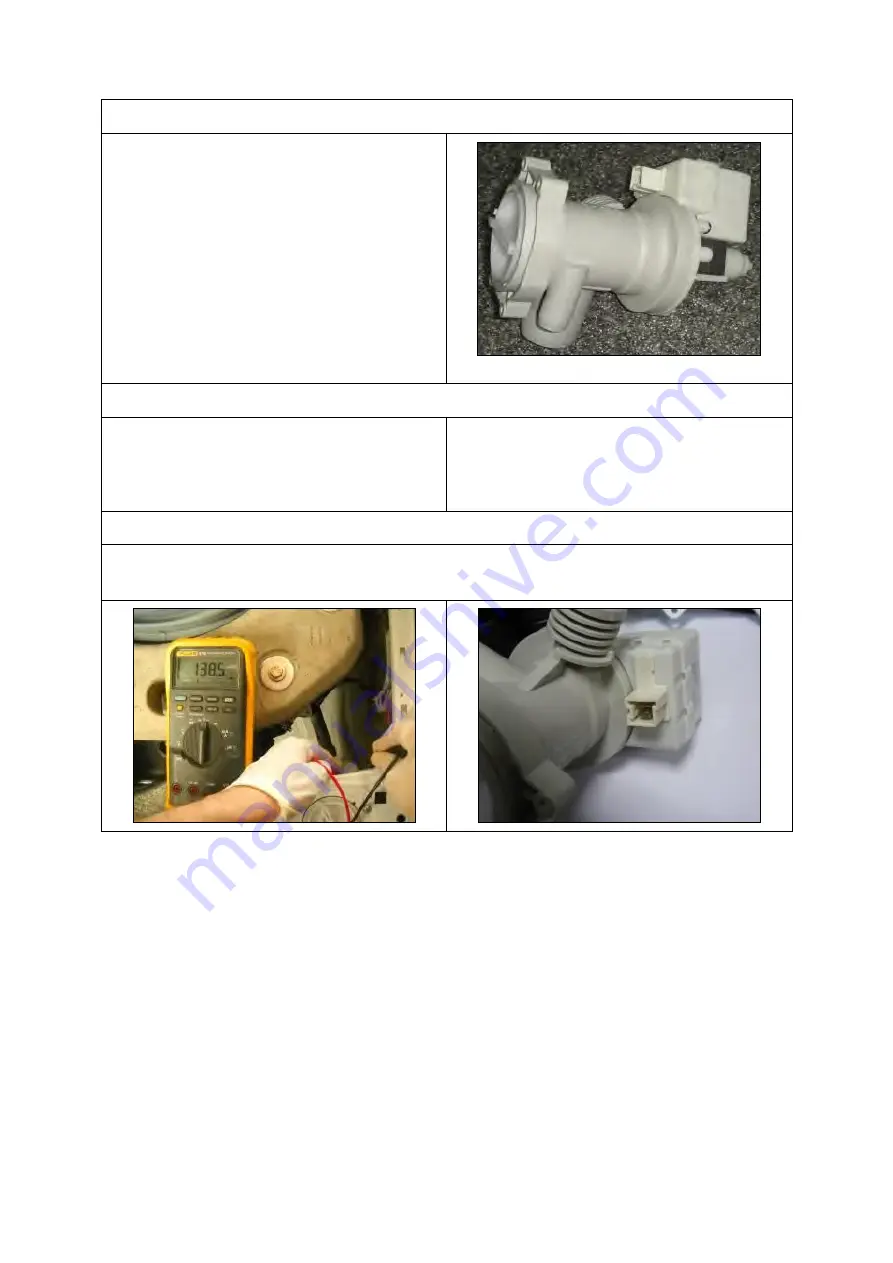
8.1. Drain Pump 

Drain  pump  is  both  a  mechanical  and  electrical 

component  which  is  used  to  drain  water  inside 

the  washing  machine.  It  has  an  synchronous 

motor 

inside. 

For 

better 

performance 

maintanance,  pump  filter  should  be  cleaned 

regularly. 


Drain pump


Technical features 

Nominal voltage 

220-240 V 

Nominal current 

0.28 A (±10 %) 

Nominal power 

30 W (±20 %) 

Frequency 

50 Hz 


Resistor (coil) 

125 Ω (±5%) 

Water flow 

17 L/min(to 1 m 
height) 

Thermal protector 

YES 


Testing component 

Check the resistance value on the component with multimeter as shown below.  

Resistance value should be between 125 Ω (±5%) 


Summary of Contents for D4 Series

Page 1: ...Manuel de service Séries D4 ...

Page 2: ...nt Drawer Housing 18 7 12 Power Cable Group and EMI Filter 18 7 13 Electronic Pressure Switch EPS 19 7 14 Door Lock 19 7 15 Drain Pump 20 7 16 Front Counterweight 20 7 17 Heater 20 7 18 Tub Bellow Seal 21 7 19 Transport Screw 21 7 20 Upper Counterweight 21 7 21 Washing Group 22 7 22 Shock Absorber Pin 22 7 23 Driven Pulley 22 7 24 Driven Pulley 22 7 25 Motor 23 7 26 Tub 23 8 Component Specificatio...

Page 3: ...onal components Information already exists in user manuals is not included in this service manual Please refer to user manual of your product for basic installation operating maintenance and troubleshooting issues Contact For your inquiries please send an email to WashingMachineCustomerSupport vestel com tr You can also open a support ticket using Service Support Page https www vestelservice com V...

Page 4: ...make sure appliance is unlplugged water tap is closed and heating elements are cooled down There is electrical shock burning and flood risk Warning Please replace whole cable group even in case there is any minor failure with cables terminals sockets Never try to repair nor to solder cable group It may cause smoke ignition and there is major risk of electrical shock Important Always use insulator ...

Page 5: ...ailable for cotton programs only Foam Protection System Foam Protection System is a safety algorithm that interrupts normal program flow and reduces foam level by taking water and draining This algorithm protects machine and environment avoiding over foaming inside tub in case any customer misuse such as detergent overdose or use of foamy cleaning agents Overflow Protection System Overflow protect...

Page 6: ...ch 2 Option 1 Delay Timer SW3 Switch 3 Option 2 Drying Level SW4 Switch 4 Spin Speed Selection SW5 Switch 5 Temperature Selection L1 LED 1 Start Pause LED L2 LED 2 Drying Level 1 LED L3 LED 3 Drying Level 2 LED L4 LED 4 Drying Level 3 LED L5 LED 5 Drying Level Option LED L6 LED 6 Delay Time LED PR SW5 SW4 SW3 SW2 SW1 ...

Page 7: ...ed Step5 The motor turns to left Step6 Both valves are activated Water intake for heating Step7 Washer NTC is checked Step8 Washer Heater is checked Step9 Dryer resistance I and I II are checked Step10 Dryer NTC is checked for 2sec Step11 Fan is checked In case of no failure test ends after this step and End is displayed In case of an error detection EXX and error definition will pop up on display...

Page 8: ...the Autotest and go to the selection mode Also if any frequency can not be detected then it means there is problem with connecion or EPS so it gives E10 which is EPS error and cancels the autotest goes to the selection mode Dryer Ntc detection Software will detect NTC s resistance value and will check if the temperature is between 0 C Tdetected 50 C If it is inside the range heating step will be d...

Page 9: ...erature change ΔT 10 C it will release E14 failure If temperature increases accordingly ΔT 10 C SAU visualization should make slow blink to indicate that the step is over You can turn program knob to 4th position to continue with step4 Step4 Dryer Heater II and fan is activated After 3 mins if there will be no temperature change ΔT 10 C it will release E14 failure If temperature increases accordin...

Page 10: ...18 NA A 6 Critical Torque Values Assembly Locatıon Bolt Nut Screw Torque Min Nm Torque Nom Nm Torque Max Nm Air Pressure Wrench Speed rpm Transport Screw Assembly Transport Screws 6 50 6 50 7 00 1000 Motor Assembly Motor Screws 6 00 6 50 7 50 800 Front Concrete Weight Front Tub Assembly Front Counterweight Screws 14 00 14 50 14 75 600 Upper Counter Weight Assembly Upper Counterweight Screws 25 00 ...

Page 11: ...wo screws that fix the top plate at the back Push the top plate back and pull it up 7 2 Door 1 2 Remove two screws that fix the door by using T25 tool Pull the door up 3 4 Remove screws that fix the door group Put the door outside plastic with helping screwdriver T25 ...

Page 12: ...or handle pin 7 3 Spring Wire 1 2 First remove the spring wire fixing the tub bellows seal by using the small size screw driver Pull the tub bellows seal Remove the tub bellows seal body fixing spring 7 4 Detergent Drawer 1 2 Gently pull the detergent drawer While pressing siphon cover keep pulling drawer to remove it ...

Page 13: ...7 5 Control Panel 1 2 Remove the screw which fixes the control panel to the front panel Remove two screws fixing control panel ...

Page 14: ...ectronic card cover as it is shown in the pictures by using small screw driver Remove the PCB card box from the control panel 7 6 Electronic Card Fuse 1 2 Remove PCB box using a small screw driver 3 4 Unplug display card connector Open fuse box and remove the fuse ...

Page 15: ... fixing the front panel at the bottom Remove two screws fixing the door lock 3 4 Remove the tub bellows seal 5 6 Remove two screws fixing front panel to body Remove the screw fixing twinjet elbow 7 8 Pull front panel up Remove front panel ...

Page 16: ...r cover Release the holder of the pump filter cover 7 8 Dryer Card 1 2 Remove the screws that fixes the dryer card Remove the sockets 7 9 Dryer Unit 1 2 Remove the screws that fixes the heater unit of the dryer Remove the sockets of the heater unit ...

Page 17: ... connection 4 5 Remove the Cable group of the dryer unit Remove the sockets of the heater group 6 7 Remove the sockets of the fan group Remove the screws that fix the fan group 8 9 Cut the connection plastic of the dryer unit Cut the cable connection of the dryer NTC and remove the sockets ...

Page 18: ...rawer Housing 1 2 Remove the tub bellow hose by releasing the holder extensions of bellow hose Unplug connectors from feed valve 3 4 Slightly turn the feed valve counter clockwise to remove Remove the detergent drawer housing assembly 7 12 Power Cable Group and EMI Filter 1 2 Remove the five conectors that is connected to the EMI filter Remove two screws fixing EMI filter ...

Page 19: ...3 4 Pull the power cable group up Remove EMI filter 7 13 Electronic Pressure Switch EPS 1 2 Unplug EPS connector Pull EPS up 3 Remove clamp from EPS hose 7 14 Door Lock 1 Unplug door lock connector ...

Page 20: ...ixing tub outlet hose 3 4 Unplug drain pump connector Remove screws holding drain pump 7 16 Front Counterweight 1 2 Remove three screws on the front counterweight Wrench size 13 mm Gently pull counterweight out 7 17 Heater 1 2 Unplug heater connectors Remove nut 8 mm fixing the heater ...

Page 21: ...Hold the tub bellows seal and gasket body fixing spring together and pull them out 7 19 Transport Screw 1 2 Remove four transport screws Hold the transport screw and pull it out 7 20 Upper Counterweight 1 2 Remove two screws fixing the upper counterweight by using box wrench size 13 mm Hold and carry upper counterweight out ...

Page 22: ...cket Remove the washing group carrying it out through front side 7 22 Shock Absorber Pin 7 23 Driven Pulley 1 1 Remove shock absorber pins squeezing the ratchet by a pliers Remove the belt rotating the driven pulley 7 24 Driven Pulley 1 1 Remove the bolt at the center of pulley by tucking a wooden bar avoids rotation Remove pulley ...

Page 23: ... up 7 26 Tub 1 2 Remove tub inlet bellow hose loosening the clamp squeezing it by using a pliers Remove screw holding EPS reservoir 3 4 Remove tub outlet bellowed hose loosening screwed clamp Remove 19 screws around tub using box wrench size 8 mm 5 6 Remove front tub Remove drum ...

Page 24: ...er performance maintanance pump filter should be cleaned regularly Drain pump Technical features Nominal voltage 220 240 V Nominal current 0 28 A 10 Nominal power 30 W 20 Frequency 50 Hz Resistor coil 125 Ω 5 Water flow 17 L min to 1 m height Thermal protector YES Testing component Check the resistance value on the component with multimeter as shown below Resistance value should be between 125 Ω 5...

Page 25: ...ons Phase notral and ground connections Resistance Technical features Heater type Tubular heating element with NTC sensor Nominal voltage 230 V Nominal power 2000 W 5 Resistance 26 4 Ω 5 Termal fuse 2 sided Testing component Check the resistance value on the component with multimeter as shown below Resistance value should be between 26 4 Ω 5 ...

Page 26: ... 10 54 9 62 6 5 43 0 48 6 0 33 9 38 1 5 27 0 30 1 10 21 6 23 9 15 17 4 19 1 20 14 1 5 4 25 11 5 12 5 30 9 4 10 2 35 7 8 8 3 40 6 4 6 9 45 5 4 5 7 Temp C R min kΩ R max kΩ 50 4 5 4 7 55 3 8 3 9 60 3 2 3 3 6 2 7 2 8 70 2 3 2 4 75 1 9 2 0 80 1 7 1 8 85 1 4 1 5 90 1 2 1 3 95 1 1 1 1 100 0 9 1 0 NTC Resistance vs NTC Temperature Testing component Check the resistance value on the component with multime...

Page 27: ...low rate washer valves 7 L min 15 Flow rate dryer valve 1 2 L min 15 Operating water pressure 1 10 bar Testing component Check the resistance value on the component with multimeter as shown below Washer valves water flow rate should be 7 L min 15 Dryer valve s water flow rate should be 1 2 L min 15 Washer valves coil resistance values should be 3750Ω 10 Dryer valve s coil resistance value should b...

Page 28: ...ine tap is connected and opened power cord is plugged Put no detergent in drawer 2 Bring porgram knob to position 1 Cotton 90 C program 3 Press start button 4 Wait for water intake step to finish You can recognise it by listening the water sound or slightly opening and observing detergent drawer 5 As soon as water intake is over turn program knoc to position 0 Off position 6 Check water level from...

Page 29: ...check the motor for correct diagnosis and quick servicing In the below picture socket points on the motor is shown to measure with multimeter Motor Motor socket terminals MOTOR CODE BRAND STATOR FULL Ω TACHO Ω STATOR HALF Ω TEMP 32013066 ANAIMEP 1 20 7 180 7 0 55 7 20 C Tacho terminals Strator Terminals ...

Page 30: ...d between 45 seconds to 85 seconds after the program end This time delay is caused by the PTC which is assembled in the door lock Door lock Technical features Nominal voltage 250 V Testing component Check the resistance value on the component with multi meter as shown in below figures Resistance value should be 1000Ω 50 at 20 C ...

Page 31: ... Fan group Technical features Nominal voltage 230 V Frequency 50 Hz Rated Power 34 W Resistance 20 C 82 7Ω 3Ω Motor speed 1300 RPM Air Flow Rate 70 m3 h Testing component Check the resistance value on the component with multi meter as shown in below figures Resistance value should be 82 7Ω 3Ω at 20 C ...

Page 32: ...nology Dryer Heater Technical features Nominal voltage 230 V Rated power Heater I 750 W Rated power Heater II 750 W Resistance 20 C 65 5 72 6 Ω Testing component Check the resistance value on the component with multi meter as shown in below figures Resistance value should be in 65 5 72 6 Ω range ...

Page 33: ... C R min kΩ R max kΩ 25 19 40 20 60 30 15 56 16 67 40 10 19 11 10 50 6 82 7 54 60 4 65 5 23 70 3 25 3 70 80 2 32 2 68 90 1 69 1 97 100 1 24 1 47 Temp C R min kΩ R max kΩ 110 0 93 1 11 120 0 70 0 85 130 0 54 0 66 140 0 42 0 52 150 0 33 0 41 160 0 26 0 32 170 0 21 0 25 180 0 17 0 20 NTC Resistance vs NTC Temperature Testing component Check the resistance value on the component with multi meter as sh...

Page 34: ...omponent Control on PCB Sockets on the PCB Scokets on the Dryer Board 8 11 1 Washer NTC NTC resistance values are checked black cables as shown Refer to the relevant table for the NTC resistance values Motor ...

Page 35: ...values are checked red cables as shown 8 11 3 Washer Valves Valve resistance value is checked with a multimeter as shown Washer valves resistance values 3750 Ω 10 Pre Wash Valve Check the red cables Main Wash Valve Check the black cables ...

Page 36: ... resistance value 125 140 Ω 8 11 5 Door Lock Resistance value is checked with a multimeter as shown Check the white and blue cables Resistance values 240Ω 20 25 C 8 11 6 Dryer NTC Component Control Check the socket at the bottom of the dryer board as shown ...

Page 37: ...9 Wiring Diagram ...

Page 38: ...ired Replace door lock Replace cable group Is door closed properly Are environmental conditions are OK Check PCB socket connections Is thee any loose socket connector Similarly check door lock connector Is it loose Are there any burr obstacle around door hook lock handle mechanism Test door lock component as explained in service manual Is door lock component OK Redo same door lock test by PCB sock...

Page 39: ...oose socket connector Similarly check valve connectors Is it loose Test valve component as explained in service manual Is valve component OK Redo same valve test by PCB sockets Is it still OK Replace PCB NO YES Environmental conditions Voltage range should be in as specified in instruction book Water pressure should be as specified in instruction book WM should be grounded properly There should be...

Page 40: ... connectors Is it loose Test pump component as explained in service manual Is pump component OK Redo same pump test by PCB sockets Is it still OK Replace PCB NO YES Environmental conditions Voltage range should be in as specified in instruction book Water pressure should be as specified in instruction book WM should be grounded properly There should be enough ventilation space from ground Other en...

Page 41: ...tors Is it loose Is there any deformation through pressure switch sensor hose Test pressure switch sensor component as explained in service manual Is pressure switch sensor component OK Replace PCB NO YES Environmental conditions Voltage range should be in as specified in instruction book Water pressure should be as specified in instruction book WM should be grounded properly There should be enoug...

Page 42: ...onmental conditions Voltage range should be in as specified in instruction book Water pressure should be as specified in instruction book WM should be grounded properly There should be enough ventilation space from ground Other environmental specifications and requirements should be met which are mentioned in instruction book of WM Replace NTC Test NTC component as explained in service manual Is N...

Page 43: ...loose Replace PCB NO YES Environmental conditions Voltage range should be in as specified in instruction book Water pressure should be as specified in instruction book WM should be grounded properly There should be enough ventilation space from ground Other environmental specifications and requirements should be met which are mentioned in instruction book of WM Replace Motor Test motor component a...

Page 44: ...loose Replace PCB NO YES Environmental conditions Voltage range should be in as specified in instruction book Water pressure should be as specified in instruction book WM should be grounded properly There should be enough ventilation space from ground Other environmental specifications and requirements should be met which are mentioned in instruction book of WM Replace Motor Test EPS component as ...

Page 45: ...d connectors Is it loose Replace PCB NO YES Environmental conditions Voltage range should be in as specified in instruction book Water pressure should be as specified in instruction book WM should be grounded properly There should be enough ventilation space from ground Other environmental specifications and requirements should be met which are mentioned in instruction book of WM Replace Cable Gro...

Page 46: ... connectors Is it loose Replace PCB NO YES Environmental conditions Voltage range should be in as specified in instruction book Water pressure should be as specified in instruction book WM should be grounded properly There should be enough ventilation space from ground Other environmental specifications and requirements should be met which are mentioned in instruction book of WM Replace Cable Grou...

Page 47: ... connectors Is it loose Replace PCB NO YES Environmental conditions Voltage range should be in as specified in instruction book Water pressure should be as specified in instruction book WM should be grounded properly There should be enough ventilation space from ground Other environmental specifications and requirements should be met which are mentioned in instruction book of WM Replace Cable Grou...

Reviews: