Paramount MX User Guide
42 |
P a g e
Versa-Plate Mounting Positions
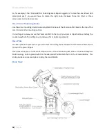
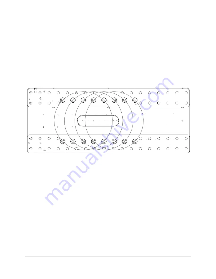
The Versa-Plate can be mounted to the top of the declination axis in four different positions and can be
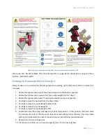
adjusted depending on the weight distribution of the payload. The gray circles in Figure 15 represent
the top of the declination axis at each mounting position.
If your payload is “camera-end heavy” mount the Versa-Plate at the forward most position so that the
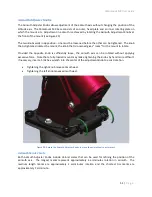
payload can be more easily balanced. Remove the four 1-inch socket head cap screws (SHCS) using a
3/16-in hex wrench, then adjust the position of the Versa-Plate accordingly. The mounting position
depends on your equipment, so there may be a bit of trial and error to find the optimal spot. The four
SHCS should be tightened snugly so that the Versa-Plate cannot wiggle or shift when carrying the
payload, but not too tight.
Figure 15: The four Versa-Plate mounting positions. (The Instrument Panel end is to the right.)
Standard versus Wide Mounting Versa-Plate Orientation
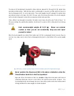
The Paramount MX is shipped with the Versa-Plate in the standard orientation. The Versa-Plate can also
be mounted at 90 degrees from the typical orientation, offering a wider mounting to accommodate
multiple optical tube assemblies.
To change the orientation of the Versa-Plate:
1.
Remove the six 1-inch ¼-20 3/16 socket head cap screws on the top of the Versa-Plate.
2.
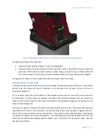
Rotate the Versa-Plate 90 degrees. The top of the declination axis has “indentations” to
accommodate the instrument panel and through the mount cabling.
3.
Align the mounting holes on the Versa-Plate with the mounting holes at the top of the
declination axis and replace four of the six screws. Only four socket head cap screws are used in
the wide orientation.


