background image

Chapter 5 - Connect to netw ork

16

TH LINK PROFINET - Installation Manual

5

Connect to network

1. Insert the patch cable plug (RJ-45, not included in the scope of

delivery) into the Ethernet socket on the device until the plug
locks into place.

2. The green LED on the Ethernet socket lights as soon as the

device is energized and a network is available.

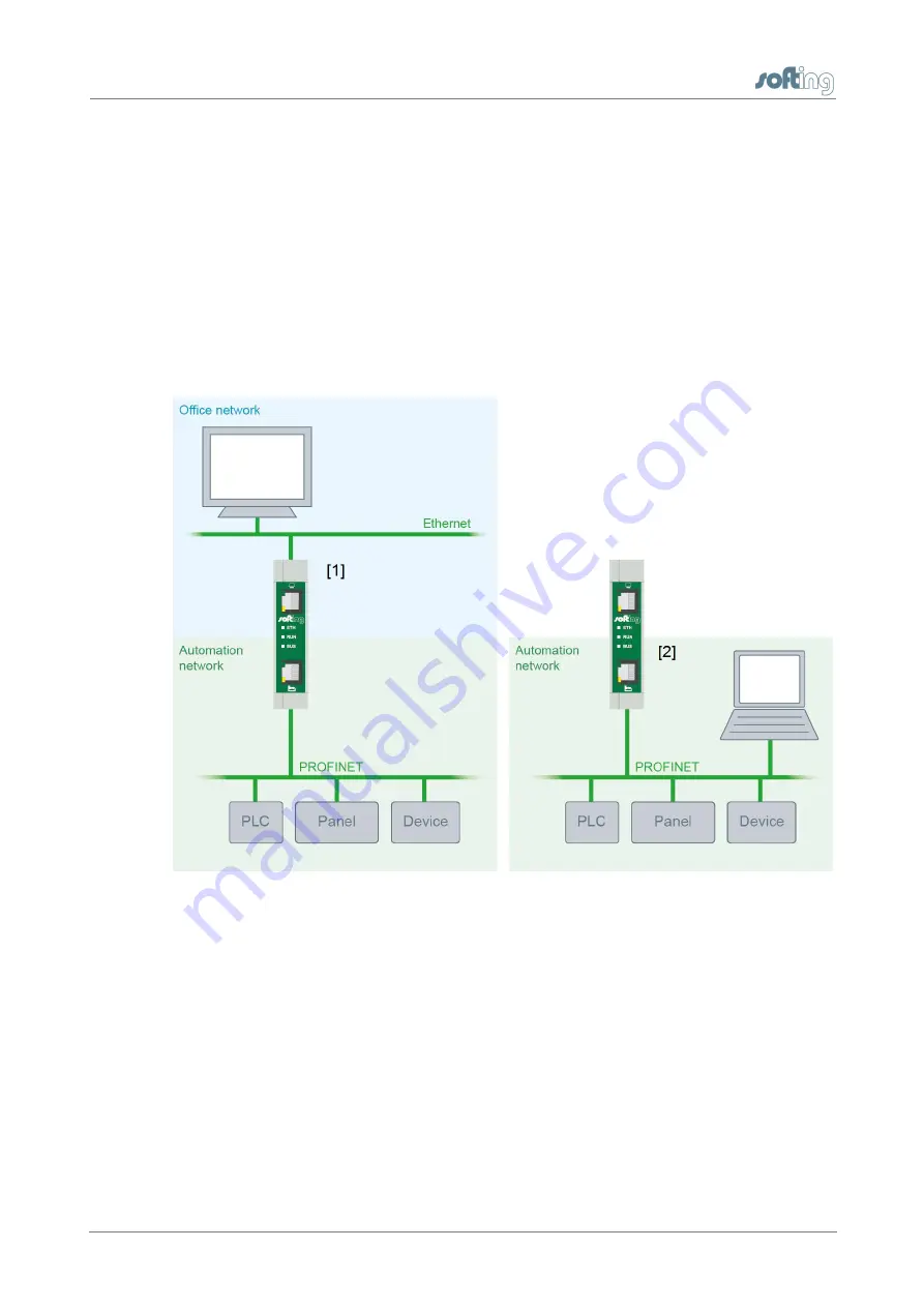
Connection options

Figure 3: Connection options

1. Secure access at separated networks - connection to office

network and automation network

a. At the upper Ethernet interface with the monitor icon (see

figure 1 no. [1]) the office network is connected, from which
the access to the automation network should be done.

b. At the lower Ethernet interface with the factory icon (see

figure 1 no. [5]) the automation network is connected that
should be monitored.

Summary of Contents for TH LINK PROFINET

Page 1: ...Copyright 2014 2015 Softing Industrial Automation GmbH TH LINK PROFINET Installation Manual Version EN 042015 1 10...

Page 2: ...r improvements to these instructions without prior notice The actual design of products may deviate from the information contained in the instructions if technical alterations and product improvements...

Page 3: ...eline Chapter 4 14 Mount unmount device 14 4 1 Mount device 15 4 2 Unmount device Chapter 5 16 Connect to network Chapter 6 18 Connecting power supply and relay contact Chapter 7 20 Configuring the de...

Page 4: ...iguration 9 1 3 26 9 2 TH SCOPE 27 Measurement 9 2 1 28 Alert 9 2 2 28 Parameter distribution 9 2 3 28 Set parameter provider 9 2 3 1 29 Apply parameters 9 2 3 2 30 Parameters 9 2 3 3 Chapter 10 31 Fi...

Page 5: ...vent network disruptions by unauthorized configuration changes all configuration functions are protected by user administration Features Secure access to the PROFINET network Basis for TH SCOPE Access...

Page 6: ...tion of the system after installation The TH LINK may only be installed or uninstalled by qualified trained electrical engineering personnel When installing the TH LINK observe the regulations for han...

Page 7: ...documentation Keys buttons menu items commands and other elements involving user interaction are set in bold font and menu sequences are separated by an arrow Open Start Control Panel Programs Buttons...

Page 8: ...r download area at http industrial softing com en downloads html 1 6 Document history Document version Release date Modifications compared to previous version 1 00 December 2014 Adaptation to new Soft...

Page 9: ...ch other 1123 1124 2364 UDP TH LINK communication with TH SCOPE via Multicast via Unicast 2364 UDP 1151 2365 UDP 1 8 Network presettings The device is preset to network operation with a DHCP server No...

Page 10: ...isplay elements Figure 1 TH LINK front and lateral view 1 Ethernet interface for office network o lights yellow Ethernet data communication o lights green physical connection available 2 LED ETH o lig...

Page 11: ...ghts green TH SCOPE measurement is running o is off TH SCOPE measurement is stopped 5 Ethernet interface for automation network o lights yellow Ethernet data communication o lights green physical conn...

Page 12: ...NK Settings TH SCOPE and set the parameter Data restore after voltage recovery to Yes see also TH SCOPE 3 Following the initial device commissioning the SD card is formatted automatically From this ti...

Page 13: ...1 Mounting see Mount unmount device 2 Plug in SD card recommended see SD card 3 Connect to network see Connect to network 4 Connect to the power supply see Connecting the power supply 5 Configure netw...

Page 14: ...ve a minimum of 5 cm below and above the TH LINK in order to ensure heat dissipation Figure 2 Mount and unmount the TH LINK 1 Device with notch on DIN rail 2 DIN rail 3 Device on DIN rail 4 Stop lever...

Page 15: ...4 2 Unmount device 1 Remove the connected supply and signal lines Ethernet power supply 2 Place the screwdriver into the stop lever on the device see figure above 3 Press the screwdriver in the direct...

Page 16: ...the device is energized and a network is available Connection options Figure 3 Connection options 1 Secure access at separated networks connection to office network and automation network a At the upp...

Page 17: ...thernet interface with the factory icon see figure 1 no 5 in the automation network b The connection of the upper Ethernet interface is not required if the access to the TH LINK is done from the autom...

Page 18: ...ure correct and proper earthing of the device Note Reverse polarity in the power supply can damage the device Make sure the power supply is connected with correct polarity Figure 4 Terminal strip for...

Page 19: ...ply and relay contact TH LINK PROFINET Installation Manual 19 3 Switch on the power supply The LED RUN is green and the LED ETH flashes red until the device s boot procedure is completed Afterwards th...

Page 20: ...ration Protocol The device is preset to network operation with a DHCP server and in this case it is automatically assigned an IP address No network configuration settings are required in this operatin...

Page 21: ...as to be in the same subnet as the TH LINK e g with the IP address 169 254 0 5 2 Start a web browser on your PC notebook 3 Enter the IP address http 169 254 0 1 and press Enter 4 Click Language and se...

Page 22: ...Enter the new addresses for Subnet mask and Default gateway Note The entry of the standard gateway is required only if you set the IP addresses for both networks manually Otherwise the standard gatew...

Page 23: ...e in the network if the device is integrated into the office and or automation network the device is supplied with voltage the PC notebook is in the office or in the automation network Procedure Start...

Page 24: ...gin 1 Proceed as described in Check the connection to the device 2 Click Login 3 Enter the password Note The default password is the nine digit serial number of the device You can find it on the seria...

Page 25: ...2 Click Settings TH LINK The TH SCOPE settings page includes all settings for monitoring the automation network This includes User administration TH LINK description and network configuration Figure...

Page 26: ...g click on the question mark 9 1 3 Network configuration Here you can change the network specific settings These include hostname configuration method for office and automation network DNS server and...

Page 27: ...of measurement the measurement range default oder user defined ranges start stop of the measurement the sorting of the diagnostics list delete of diagnostics messages the additional SNMP community na...

Page 28: ...herefore one TH LINK has to be set a parameter provider All other units can request the parameters from this device 9 2 3 1 Set parameter provider The TH LINK from which all other units can take over...

Page 29: ...tings TH SCOPE 3 On Parameter distribution Apply parameters click Request to request the parameters from the parameter provider 4 The TH LINK restarts and you will be logged out as administrator autom...

Page 30: ...are transferred TH LINK o Default language o DNS server settings o Time server settings PC system time after synchronization TH SCOPE o Measurement type o Measurement o Sorting of diagnostics list o...

Page 31: ...n Firmware Update 3 Check if the requirements for a firmware update are met Stop the current measurements and the external application 4 Download the latest firmware version from http industrial softi...

Page 32: ...ration with a DHCP server IP address for the device is assigned by the DHCP server If your network server does not support DHCP you need to set the IP address for the TH LINK manually see Connection i...

Page 33: ...ximum current consumption on turn on is limited to 8 A in the TH LINK Operating conditions Ambient temperature range C 40 75 Relative humidity 5 95 no condensation Depending on the SD card used the am...

Page 34: ...12 Technical Data 34 TH LINK PROFINET Installation Manual Housing dimensions Dimensions W H D mm 22 5 99 114 5 Weight approx g 120 Other Ethernet connection Type RJ 45 10Base T 100Base TX Certificate...

Page 35: ...This page is intentionally left blank...

Page 36: ...r Allee 6 85540 Haar Germany Tel 49 89 4 56 56 0 Fax 49 89 4 56 56 488 Internet http industrial softing com Email info automation softing com Support support automation softing com Softing Industrial...

Reviews: