19
EN
SUNSYS PCS2 Power Conversion System and Storage from 33 to 200 kVA - Ref.: IOMSUNPCXX04-EN 01
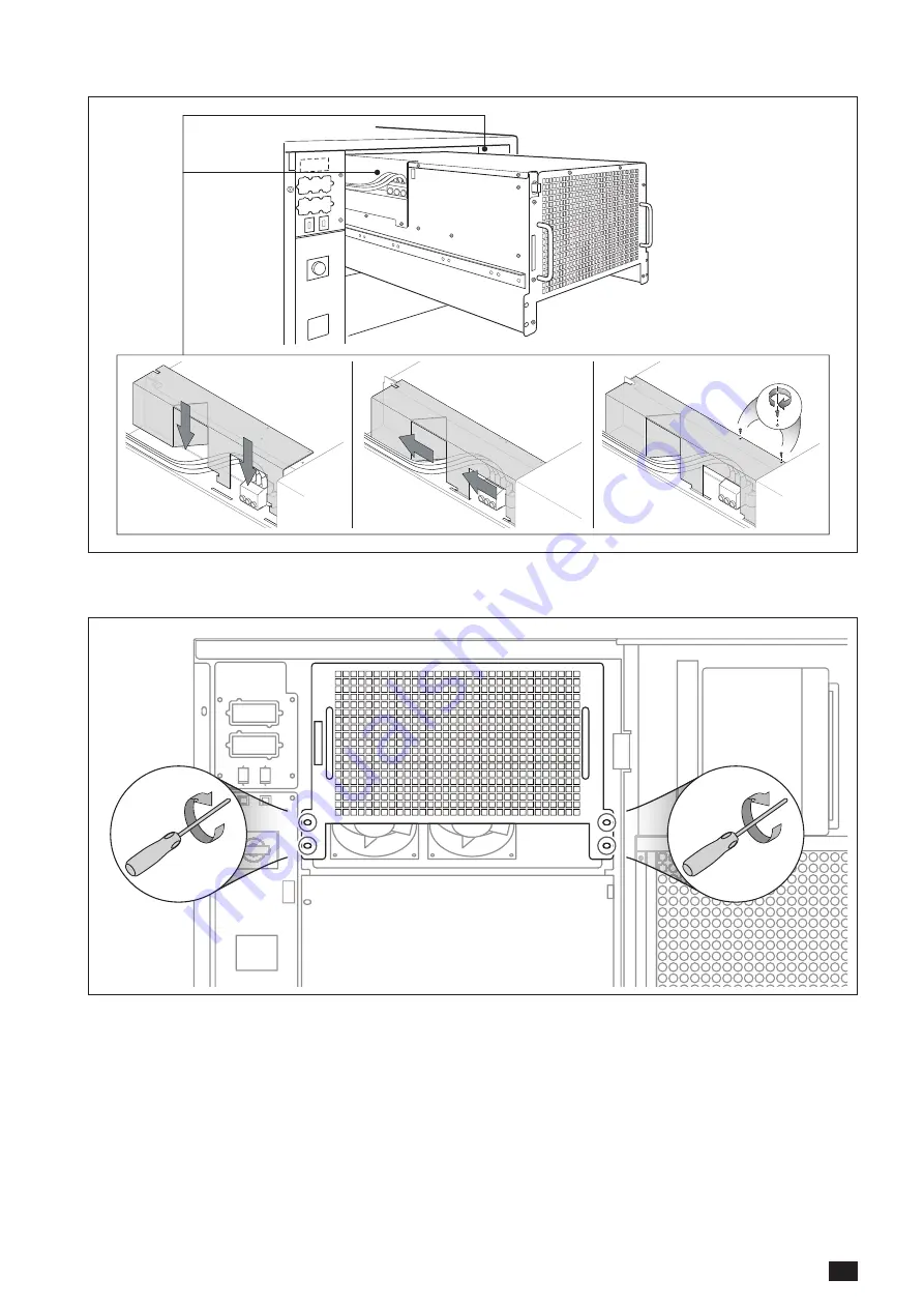
• Position the Lexan protection and secure it.
• Insert the module completely.• Tighten the screws to secure the module to the SUNSYS PCS
2
.
Page 1: ...SUNSYS PCS2 Power Conversion System and Storage from 33 to 200 kVA EN INSTALLATION AND OPERATING MANUAL www socomec com...
Page 2: ......
Page 3: ...ES 33 7 2 DIAGRAM OF MAIN SYSTEM EXAMPLE FOR VERSION 100 TR 45 8 CONNECTIONS 46 8 1 INPUT CONNECTION 46 8 2 INSTRUCTIONS FOR SUNSYS PCS2 TL VERSION 53 9 CONTROL PANEL 54 9 1 EXCEPTION FOR PCS2 132 200...
Page 4: ......
Page 5: ...tion thereof Defective items replaced free of charge shall be made available to SOCOMEC and shall become its property Items invoiced as appropriate to the CUSTOMER shall be warranted 3 three months in...
Page 6: ...warm place wait approx two hours before putting the unit into operation NOTE When carrying out electrical installation all standards applicable specified by the IEC and the electricity supplier must b...
Page 7: ...ings on labels and plates on the equipment Symbols Description Protective earth terminal PE Authorised personnel only No smoking Risk of electric shock Risk of explosion Avoid short circuits Read the...
Page 8: ...Energy Management System ESS Energy Storage System HMI Human Machine Interface IEC International Electrotechnical Commission IM Islanding Mode IMD Insulation Monitoring Device PCS Power Conversion Sy...
Page 9: ...n limit the impact of increases in the electricity retail price by supplying the load to cut peak demand peak shaving maximising PV energy self consumption at building or community level Any PV energy...
Page 10: ...ent of grid operators thanks to voltage and frequency regulation load shifting peak shaving and ancillary services for grid support 3 Microgrids Ensure energy availability and quality The SUNSYS PCS I...
Page 11: ...PCS SUNSYS PCS IM 33 kVA 66 kVA 100 kVA 132 kVA 200 kVA 33 kVA 66 kVA 100 kVA 132 kVA 200 kVA Internal transformer TR version External transformer TL version 4 2 UL VERSIONS SUNSYS PCS SUNSYS PCS IM...
Page 12: ...formation regarding ambient temperature dimensions and weights refer to Technical specifications chapter To position the unit correctly see the diagrams below ROOM POSITIONING Top view Free area SUNSY...
Page 13: ...G AIR FLOW Typical air extraction structure SUNSYS PCS2 hood air air extractor external environment internal environment 10 cm Minimum air extractor flow 1 Models Minimum extraction flow 33 TR 600 m3...
Page 14: ...sible to the installation site WARNING HEAVY WEIGHT Move the unit using a fork lift truck taking the utmost caution at all times The unit MUST be handled by at least two people The people MUST take po...
Page 15: ...orage from 33 to 200 kVA Ref IOMSUNPCXX04 EN 01 5 3 FLOOR ASSEMBLY PCS2 range 33 TR 66 100 TR TL Remove the protective cover 30 cm SUNSYS PCS2 Rear PCS2 132 200 TL Level adjustment and floor fixing Le...
Page 16: ...people 30 5 kg 67 2 lb WARNING RISK OF TIPPING OVER before carrying out any operations ensure the SUNSYS PCS2 is secured at the feet WARNING RISK OF TIPPING OVER the modules must be inserted from the...
Page 17: ...UNSYS PCS2 Power Conversion System and Storage from 33 to 200 kVA Ref IOMSUNPCXX04 EN 01 Position the cables in the hose clamp to enable correct module insertion Remove the Lexan protection on the con...
Page 18: ...NPCXX04 EN 01 Place the module on the guides and insert it up to the limit starting by the lower one In order to ensure the safety of installers installers shall be at least two people to process the...
Page 19: ...CS2 Power Conversion System and Storage from 33 to 200 kVA Ref IOMSUNPCXX04 EN 01 Position the Lexan protection and secure it Insert the module completely Tighten the screws to secure the module to th...
Page 20: ...20 EN SUNSYS PCS2 Power Conversion System and Storage from 33 to 200 kVA Ref IOMSUNPCXX04 EN 01 Connect the communication cable Communication cable...
Page 21: ...01 5 4 2 PROCEDURE FOR PCS2 132 200 TL Open the doors With the appropriate key A open the lock then pull the hook B and open the right door Unhook the upper latch C and lower latch D and open the left...
Page 22: ...UNSYS PCS2 Power Conversion System and Storage from 33 to 200 kVA Ref IOMSUNPCXX04 EN 01 Position the cables in the hose clamp to enable correct module insertion Remove the Lexan protection on the con...
Page 23: ...YS PCS2 Power Conversion System and Storage from 33 to 200 kVA Ref IOMSUNPCXX04 EN 01 Insertion of the lower three modules Place the module on the guides and insert it up to the limit starting by the...
Page 24: ...The Socomec shelf can be used to facilitate the insertion of the upper three modules The shelf can be used only by persons authorized by Socomec Keep this shelf available to service people for commis...
Page 25: ...25 EN SUNSYS PCS2 Power Conversion System and Storage from 33 to 200 kVA Ref IOMSUNPCXX04 EN 01 Make sure the shelf is properly assembled 1 Place the module on the shelf 30 5 kg 67 2 lb...
Page 26: ...26 EN SUNSYS PCS2 Power Conversion System and Storage from 33 to 200 kVA Ref IOMSUNPCXX04 EN 01 Place the module on the guides and insert it up to the limit Insert the connectors and secure them...
Page 27: ...27 EN SUNSYS PCS2 Power Conversion System and Storage from 33 to 200 kVA Ref IOMSUNPCXX04 EN 01 Position the Lexan protection and secure it Insert the module completely Remove the shelf...
Page 28: ...er Conversion System and Storage from 33 to 200 kVA Ref IOMSUNPCXX04 EN 01 Tighten the screws to secure the module to the SUNSYS PCS2 In PCS2 132 TL the unused slots are covered with a panel do not re...
Page 29: ...29 EN SUNSYS PCS2 Power Conversion System and Storage from 33 to 200 kVA Ref IOMSUNPCXX04 EN 01 Connect the communication cable Communication cable...
Page 30: ...ose the left door and hook it with the both upper latch C and lower latch D Close the right leaf and close the hook B until the first clack The door is locked but the lock is not activated To lock the...
Page 31: ...200 A type C Insulation Monitoring Device IMD 100 TL 250 A type C 132 TL 315 A type C 200 TL 500A type C 1 It is advisable to carry out a preliminary check on the earth current leakage with the PCS i...
Page 32: ...voltages in category III installations protective SPDs must be provided for the AC power supply network The SPD AC option designed to protect against category III overvoltages can be fitted directly...
Page 33: ...disconnection switch Q1 Module A input disconnection switch Detail 2 Detail 1 Module A SPD AC 1 Detail 1 Detail 2 disconnection switches with fuse RS232 485 Button TEST option RS232 Button RESET optio...
Page 34: ...ion System and Storage from 33 to 200 kVA Ref IOMSUNPCXX04 EN 01 WIRING DIAGRAM FOR SUNSYS PCS2 33 TR Option IMD 3Ph PE DC Q1A Q3A T1 K1 Q70 X90 X10A Batteries AC main network Option SPD IN Option SPD...
Page 35: ...e B input disconnection switch Q1 Module A input disconnection switch Detail 2 Detail 1 Module A Module B SPD AC 1 Detail 1 Detail 2 disconnection switches with fuse RS232 485 Button TEST option RS232...
Page 36: ...rage from 33 to 200 kVA Ref IOMSUNPCXX04 EN 01 WIRING DIAGRAM FOR SUNSYS PCS2 66 TR DC DC 3Ph PE X10A X10B Q1B Q3B X90 Q70 Q3A T1 K1 Q1A Option IMD Option SPD OUT Common DC Batteries Batteries AC main...
Page 37: ...nection switch Q70 SUNSYS PCS2 output disconnection switch IEC320 AUX output for assistance IEC320 AUX power input Detail 2 Detail 1 Module A Module B Module C Detail 1 Detail 2 disconnection switches...
Page 38: ...IRING DIAGRAM FOR SUNSYS PCS2 100 TR 3Ph X10 T1 Q70 X90 3Ph PE K1 3Ph PE X90 Q3A Q3B DC DC DC Q1B Q1C Q1A X10B X10C X10A Q3C Batteries Batteries Batteries AC main network AC main network Power supply...
Page 39: ...h IEC320 AUX output for assistance IEC320 AUX power input Detail 2 Detail 1 Module B Module C Detail 1 Detail 2 disconnection switches with fuse RS232 485 Button TEST option RS232 Button RESET option...
Page 40: ...ystem and Storage from 33 to 200 kVA Ref IOMSUNPCXX04 EN 01 WIRING DIAGRAM FOR SUNSYS PCS2 66 TL DC DC X10A X10B Q1B Q3B X90 Q3A Q1A 3Ph PE Batteries Batteries Option SPD IN Option IMD AC main network...
Page 41: ...Module A output disconnection switch IEC320 AUX output for assistance IEC320 AUX power input Detail 2 Detail 1 Module A Module B Module C Detail 1 Detail 2 disconnection switches with fuse RS232 485 B...
Page 42: ...age from 33 to 200 kVA Ref IOMSUNPCXX04 EN 01 WIRING DIAGRAM FOR SUNSYS PCS2 100 TL 3Ph PE X90 Q3A Q3B DC DC DC Q1B Q1C Q1A X10B X10C X10A Q3C Batteries Batteries Batteries AC main network Option SPD...
Page 43: ...connection switch Q3 Module D output disconnection switch Q3 Module E output disconnection switch Q3 Module F output disconnection switch IEC320 AUX output for assistance IEC320 AUX power input RS232...
Page 44: ...to 200 kVA Ref IOMSUNPCXX04 EN 01 WIRING DIAGRAM OF SUNSYS PCS2 132 200 TL Batteries Batteries AC main network Option SPD OUT Option SPD IN Option SPD IN AC terminals DC terminals 1 2 1 Module A not...
Page 45: ...EM EXAMPLE FOR VERSION 100 TR The SUNSYS PCS system is constructed using power electronics modules Each power module incorporates circuit protection sine filter cooling fans and EMI filtering as shown...
Page 46: ...connected to the AC mains via the AC power terminals Remove the panels protecting the connection area in front of the terminals Remove the horizontal support in order to facilitate the cable connecti...
Page 47: ...bridging connections between transformer cabinet and PCS2 only for 100 TR AC neutral is not used in this Power Conversion System If desired fix the cables to the cable support guide using cable strapp...
Page 48: ...al cables Key L1 L2 L3 Connection terminals for the main AC network 3N Connection terminal for the protective earth wire L L DC connection terminals for the batteries SUNSYS PCS2 66 TL L1 L3 PE L2 L L...
Page 49: ...re L L DC connection terminals for the batteries SUNSYS PCS2 132 200 TL L L L L L1 L3 PE L2 Key L1 L2 L3 Connection terminals for the AC mains 3 phase Connection terminal for the protective earth wire...
Page 50: ...2 Power Conversion System and Storage from 33 to 200 kVA Ref IOMSUNPCXX04 EN 01 For safety reason the mounting of the protecting panels is compulsory SUNSYS PCS2 range 33 TR 66 100 TR TL 3 2 1 SUNSYS...
Page 51: ...51 EN SUNSYS PCS2 Power Conversion System and Storage from 33 to 200 kVA Ref IOMSUNPCXX04 EN 01 Fix both the lateral bases SUNSYS PCS2 132 200 TL...
Page 52: ...terface protection jumper OPTIONAL INPUT FOR EXTERNAL INTERFACE PROTECTION If local electricity supply company connection rules specify that external interface protection must be used the exter nal pr...
Page 53: ...PCS2 to mains The main technical characteristics are outlined in the following specification Ratings Parameter 66 TL 100 TL 132 TL 200 TL Rated power 70 kW 105 kW 140 kW 210 kW Rated frequency 50 Hz N...
Page 54: ...button Scrolls up through the available menus values DOWN button Scrolls down through the available menus values ENTER button Accesses the currently displayed menu accepts sends configurations and co...
Page 55: ...per three power modules Module A Module B Module C the lower one controls the lower three power modules Module D Module E Module F So the first start up procedure must be applied to both control panel...
Page 56: ...ccessful check of the battery conditions On the control panel the battery icon is green or yellow if a Battery Warning is present 1 and the number of powered on power modules appears From the SYSTEM R...
Page 57: ...hrough the SUNSYS PCS2 s first start up procedure The most important steps are described below LANGUAGE SETTING ACTIVATION CODE The Activation code four digit code must be entered to operate the SUNSY...
Page 58: ...0 kVA Ref IOMSUNPCXX04 EN 01 DATE TIME SYSTEM SETUP Set the number of modules installed 1 2 or 3 TRANSFORMER TYPE Set the type of transformer connected to SUNSYS PCS2 SOCOMEC if standard transformer i...
Page 59: ...ibility is always being upgraded please contact SOCOMEC for grid code compatibility subject to change without notice NOTE Once the country grid code has been set the SUNSYS PCS2 will be automatically...
Page 60: ...CS2 and Battery System Alarms area Alarms area Present when an alarm is active Enter ALARMS menu to display the complete alarms list Status icons Key icon Displayed if the keypad has been locked Time...
Page 61: ...SUNSYS PCS2 warning flagged red icon SUNSYS PCS2 alarm flagged Battery status SOC 87 5 62 5 SOC 87 5 37 5 SOC 62 5 12 5 SOC 37 5 SOC 12 5 Instant power level 10 60 20 70 30 80 40 90 50 90 Green Yello...
Page 62: ...ll production data RESTART DISPLAY Restart display SISTEM CONFIG Start config procedure SETTINGS PREFERENCES LANGUAGE DATE AND TIME BUZZER DISPLAY PASSWORDS SYSTEM CONFIGURATION Local remote control N...
Page 63: ...in the following sequence ESC UP DOWN ENTER To unlock the keypad the buttons must be pressed in the reverse sequence ENTER DOWN UP ESC These sequences only work on the Mimic Panel page ENTERING PASSWO...
Page 64: ...ted with FAT16 or FAT32 Step 1 The language file to be installed must be copied onto a USB stick and placed in the standard folder USB stick socomec wyhi Step 2 Insert the USB stick into the USB port...
Page 65: ...e COMMANDS The menu contains a list of commands that the user can activate through the display Local Procedure Charge discharge battery Stop procedure Calibration procedure of SUNSYS PCS2 Commissionin...
Page 66: ...Power Conversion System and Storage from 33 to 200 kVA Ref IOMSUNPCXX04 EN 01 12 OPERATING PROCEDURES NOTE before carrying out any operations on the unit read the Safety standards chapter care fully...
Page 67: ...and 200kW If the auxiliary power supply also needs to be cut off disconnect the cable from the auxiliary power supply input socket or break the fuse connection This procedure will switch off all the a...
Page 68: ...nd sudden power surges have occurred SUNSYS PCS2 must comply with the starting time of the modules before reaching the required set point operating value Energy Saver ensures system availability and s...
Page 69: ...ion Available as standard ADC card Communication Available as standard Communication card Communication Available as option 1 Only for 33 66 100 TR and 132 200 TL 14 1 SERIAL COMMUNICATION INTERFACE R...
Page 70: ...132 200 TL RS232 485 JBUS RS232 RS232 485 JBUS RS232 3 4 5 2 1 8 9 7 6 RS232 pin key 1 Reserved 2 RX for RS232 3 TX for RS232 4 Reserved 5 GND for RS232 6 Not connected 7 RTS 8 CTS 9 12V RS232 485 C1...
Page 71: ...menu SETTINGS CONNECTIVITY PERIPHERALS NETWORK PARAMETERS to Enable Disable DHCP setting Restart the HMI after modifying the parameters IP Addresses can be changed only if DHCP is disabled SUNSYS PCS...
Page 72: ...ct on IN 1 on the ADC board Send the Alarms Reset command The configuration and the designation of function for the card s IN OUT depends on the kind of batteries connected to the SUNSYS PCS2 whose co...
Page 73: ...RS232 DB9 and RS485 connectors are available on the card RTX RTX R RTX RTX RTX 1 1 2 2 3 3 4 4 5 5 6 6 7 7 8 8 9 9 Isolated Serial RS232 DB9 Isolated RS485 1 Reserved 2 RX for RS232 3 TX for RS232 4...
Page 74: ...sion System and Storage from 33 to 200 kVA Ref IOMSUNPCXX04 EN 01 14 5 SIGNAL CABLES ROUTE PCS2 132 200 TL Cable fixing points Signal conduct Power terminal area WARNING Signal cables must not entry i...
Page 75: ...er set point is too low to charge battery Increase the value of active power set point to allow correct battery charging current W22 Battery Current Derating in progress Charge discharge power is de r...
Page 76: ...ondition ing system in the unit room A15 Incorrect system configura tion System configuration wrong Check the configuration setting A22 Battery Overvoltage Battery voltage too high Check the battery c...
Page 77: ...istics on the conditions of use of the battery for analysis Expected battery lifetime is very much dependent on operating conditions Number of charging and discharging cycles Load rate Temperature NOT...
Page 78: ...tances can leak into the groundwater and get into the food chain damaging health and wellbeing Depleted batteries are considered as toxic waste When battery replacement becomes necessary only give run...
Page 79: ...66 100 132 200 Maximum power kW 36 3 72 6 110 72 6 110 145 5 220 Rated apparent power kVA 33 66 100 66 100 132 200 Maximum apparent power kVA 36 3 72 6 110 72 6 110 145 5 220 Rated voltage 1 Vrms 3 p...
Page 80: ...mperature C 5 to 60 Relative humidity 5 to 95 condensation free Cooling system Smart cooling Required cooling capacity m3 h 480 1280 1760 960 1440 1742 2880 Acoustic noise at 1 m dB 60 64 65 67 Altitu...
Page 81: ......
Page 82: ......
Page 83: ......
Page 84: ...nce 80countries where our brand is distributed 8production sites q France x3 q Italy q Tunisia q India q China x2 27subsidiaries q TRSQ KH q DKFHTL q GHM q Q MBD q DQL MX q MCH q S KX q DSGDQK MCR q N...