Page 28 / 28
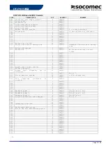
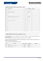
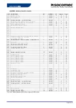
ENABLED CONTROLS TABLE: Address 0x05C0, 2 words
CODE DESCRIPTION
BIT
ADDRESS
REMARKS
C00
0
C01
1
C02
2
C03
Eco-mode enabled
3
0x05C0
C04
Mode normal enabled
4
0x05C0
C05
5
C06
6
C07
7
C08
8
C09
9
C10
Automatic Bypass transfer enabled
10
0x05C0
C11
Inverter transfer enabled
11
0x05C0
C12
12
C13
13
C14
14
C15
15
C16
Battery test enabled module 1
0
0x15C1
C16
Battery test enabled module 2
0
0x25C1
C16
Battery test enabled module 3
0
0x35C1
C16
Battery test enabled module 4
0
0x45C1
C16
Battery test enabled module 5
0
0x55C1
C16
Battery test enabled module 5
0
0x65C1
Remark: A bit set to 0 means that the control is disabled by the UPS. The control will be not executed.
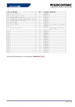
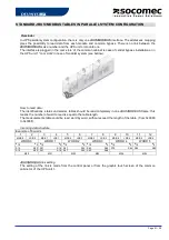
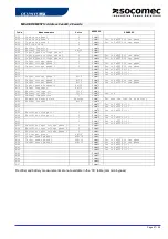
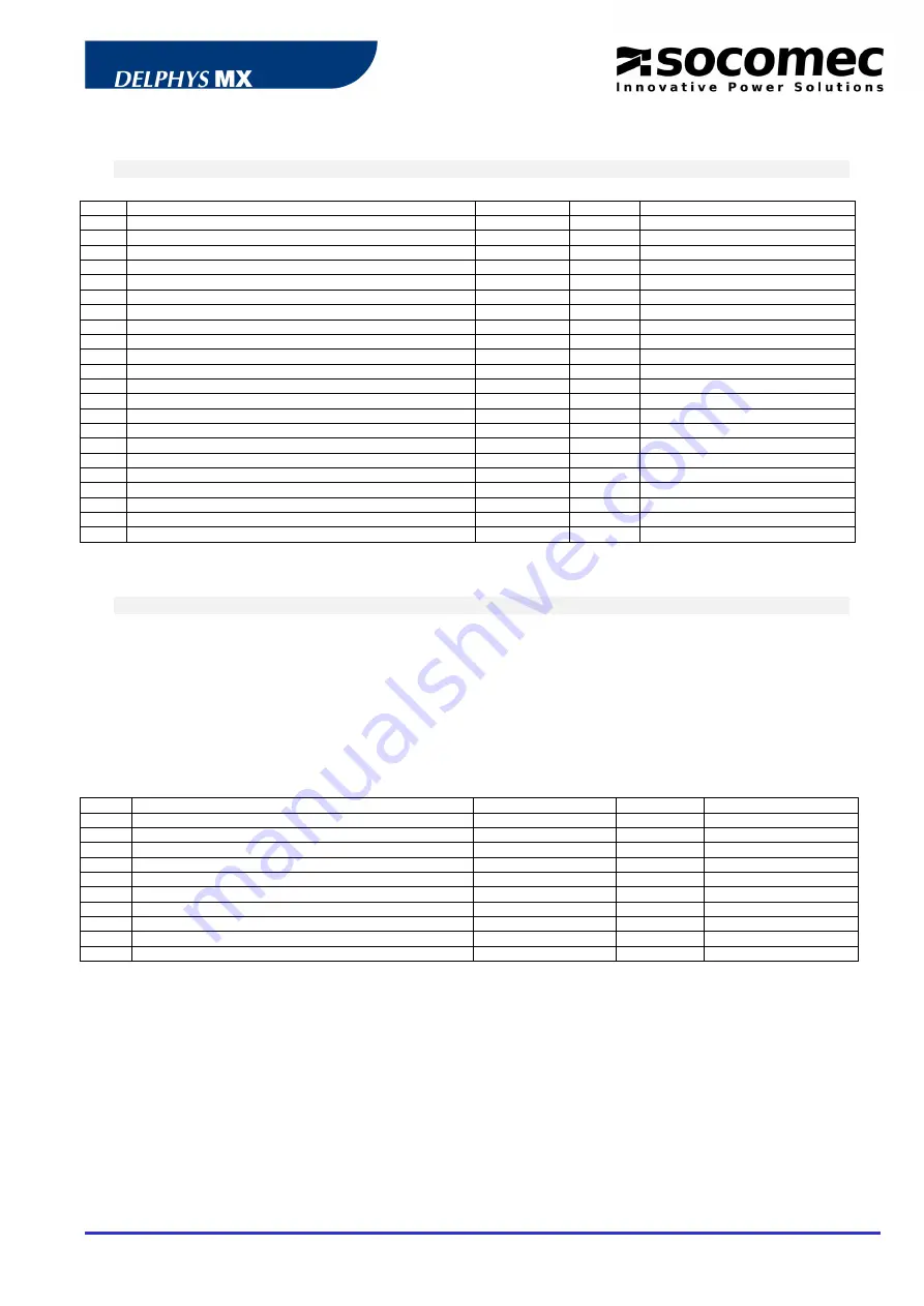
TO SEND CONTROL TO UPS: Address 0x05B0, write 1 words
For a remote UPS control, it is necessary to set the serial interface in “remote” mode using the Human
Machine Interface.
Local controls of the control panel or graphic touch screen are no more available.
The control table below shows if the selected control is allowed or not. If the control sent to the UPS is not
allowed, the function will be ignored.
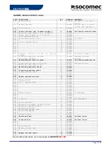
Controls available by JBUS/MODBUS connection:
Code
Control
Value to write
ADDRESS
REMARKS
C03
Eco-mode
0x0003
0x05B0
C04
Normal mode
0x0004
0x05B0
C10
Automatic bypass transfer
0x000A
0x05B0
C11
Inverter transfer
0x000B
0x05B0
C16
Battery Test module 1
0x0010
0x15B0
C16
Battery Test module 2
0x0010
0x25B0
C16
Battery Test module 3
0x0010
0x35B0
C16
Battery Test module 4
0x0010
0x45B0
C16
Battery Test module 5
0x0010
0x55B0
C16
battery Test module 6
0x0010
0x65B0


