- 9 -
3.2.2
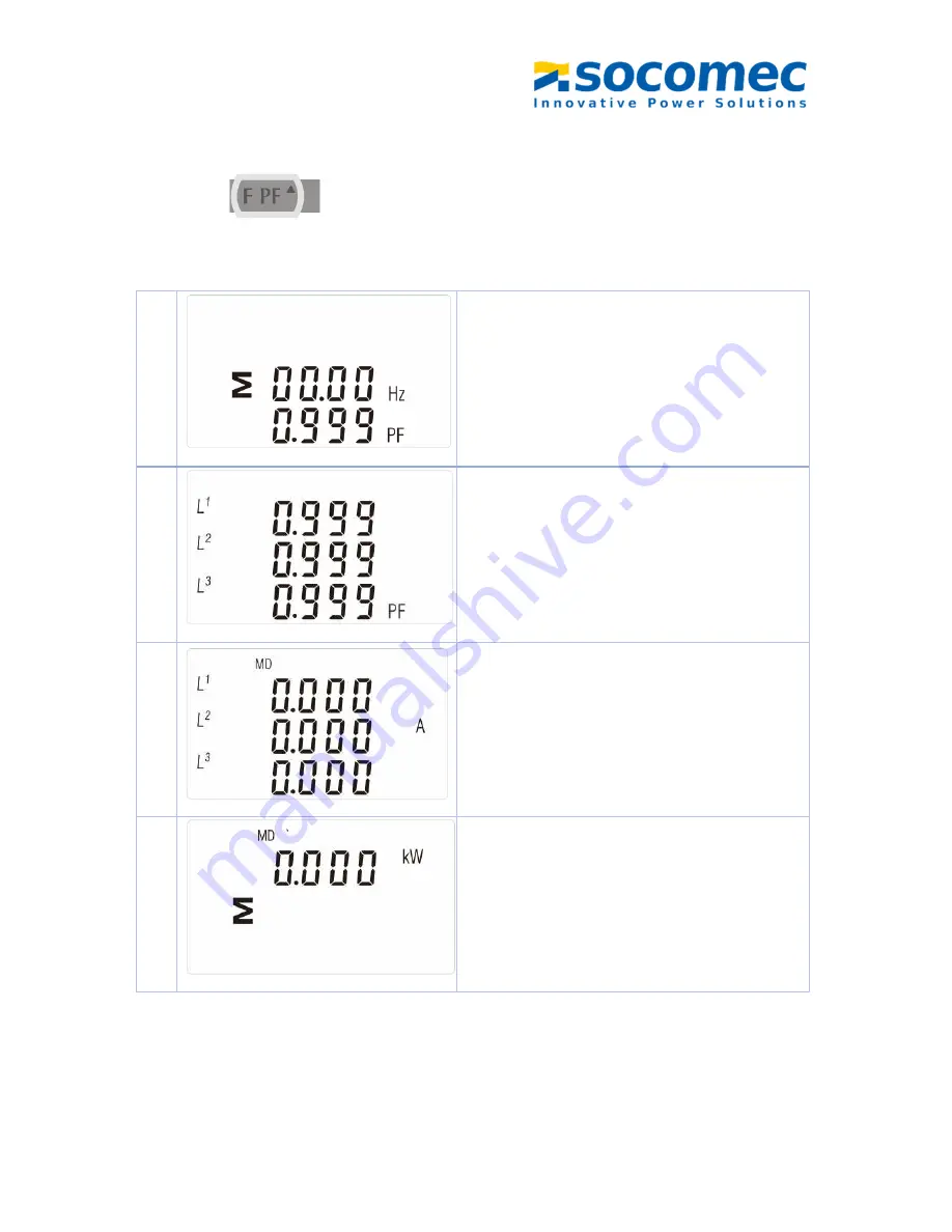
Frequency, Power Factor & Demand
Press button
:
1
Frequency and Power Factor (total)
2
Power Factor of each phase
3
Maximum Current Demand
4
Maximum Power Demand
Page 1: ...SOCOMEC CHINA CO Ltd SOCOMEC CHINA CO Ltd SOCOMEC CHINA CO Ltd SOCOMEC CHINA CO Ltd http www socomec com THREE PHASE DIN RAIL ENERGY METER COUNTIS M33 MANUAL V1 0...
Page 2: ...sages and chapters in this manual shall not be copied or reproduced or disseminated in any form Otherwise all consequences shall be borne by the violator Socomec reserves all legal rights Socomec rese...
Page 3: ...ions 3 2 2 Accuracy 3 2 3 RS485 Communication 4 2 4 Environment 4 2 5 Dimendions 5 2 6 Wiring Diagram 6 Part 3 Operation Instructions 3 1 Display and Operation 7 3 1 1 Button Definition 7 3 2 Measurem...
Page 4: ...Modbus Address 15 3 3 5 Baud Rate 15 3 3 6 Parity 16 3 3 7 Stop bit 17 3 3 8 Pule Output 17 3 3 9 Pulse Constant 18 3 3 10 Pulse Duration 19 3 3 11 Set DIT 20 3 3 12 Set backlit lasting time 21 3 3 13...
Page 5: ...irect connection saves the cost and avoid the trouble to connect external CTs giving the unit a cost effective and easy operation Built in interfaces provides pulse and RS485 Modbus RTU outputs Config...
Page 6: ...TIS M33 is a multi functional three phase energy meter designed for power system public facilities industrial applications and residential power monitoring needs It can also be used in AC charging pil...
Page 7: ...stand 20 Imax for 0 5s Operational frequency Rated 50 60Hz Range 45 65 Hz Insulation capabilities AC voltage withstand 4KV 1min Impulse voltage withstand 6kV 1 2 S waveform Internal Power Consumption...
Page 8: ...s Modbus Address 1 247 Bus load 64pcs Communication distance 1000m Parity EVEN ODD NONE Data bit 8 Stop bit 1 2 4 Environment Operating humidity 90 Storage humidity 95 Operating temperature 25 55 Stor...
Page 9: ...5 Insulating encased meter of protective class II Altitude 2000m 2 5 Dimensions 35mm Height 66 mm Width 72 mm Length 100 mm...
Page 10: ...6 2 6 Wiring Diagram 3P4W 3P3W 1P2W...
Page 11: ...n 3 Self checking finish 3 1 1 Button Definition 3 2 Measurement 3 2 1 Voltage Current Press button Selects V and A display screen In Set up Mode it is the Left or Back button Selects Hz and PF displa...
Page 12: ...8 1 Phase to neutral voltages 3p4w 1 1 Phase to neutral voltages 3p3w 2 Current on each phase 3 Phase to neutral voltage THD 3p4w 4 Current THD for each phase...
Page 13: ...9 3 2 2 Frequency Power Factor Demand Press button 1 Frequency and Power Factor total 2 Power Factor of each phase 3 Maximum Current Demand 4 Maximum Power Demand...
Page 14: ...10 3 2 3 Power Press 1 Instantaneous Active Power in kW 2 Instantaneous Reactive Power in kVAr 3 Instantaneous Volt amps in KVA 4 Total kW kVAr kVA...
Page 15: ...11 3 2 4 Energy Press button 1 Total active energy in kWh 2 Total reactive energy in kVArh 3 Imported active energy in kWh 4 Exported active energy in kWh...
Page 16: ...3 3 Setting by button o enter set up mode pressing the button for 3 seconds until the password screen appears Setting up is password protected so you must enter the correct password default 1000 befo...
Page 17: ...uttons If not there may be a further layer 4 Having selected an option from the current layer press to confirm your selection The SET indicator will appear 5 Having completed a parameter setting press...
Page 18: ...cator appears after the last digit has been set 3 After setting the last digit press to exit the number setting routine The SET indicator will be removed 3 3 3 Set Password 1 Use the and to choose the...
Page 19: ...Modbus Address The range is from 001 to 247 1 From the Set up menu use and buttons to select the Address ID 2 1 Press button to enter the selection routine The current setting will be flashing 2 2 Us...
Page 20: ...Baud Rate option 2 1 Press to enter the selection routine The current setting will flash 2 2 Use and buttons to choose Baud rate 2 4k 4 8k 9 6k 19 2k 38 4k 3 3 6 Parity Options EVEN ODD NONE 1 From th...
Page 21: ...menu use and buttons to select the Stop Bit option 2 Press to enter the selection routine The current setting will flash Use and buttons to choose Stop Bit 2 or 1 Note Default is 1 and only when the...
Page 22: ...d buttons to select the Pulse output option 2 Press to enter the selection routine The unit symbol will flash Use and buttons to choose kWh or kVArh On completion of the entry procedure press to confi...
Page 23: ...current setting will flash Note When it s dFt it means 2 5Wh VArh 2 Use and buttons to choose pulse rate On completion of the entry procedure press to confirm the setting and press to return to the ma...
Page 24: ...ting will flash Use and buttons to choose pulse width On Completion of the entry procedure press to confirm the setting and press to return to the main set up menu 3 3 11 Demand Integration Time This...
Page 25: ...val will flash Use and buttons to select the time required Press to confirm the selection SET indicator will appear Press to exit the DIT selection routine and return to the menu 3 3 12 Set backlit la...
Page 26: ...eing monitored 1 From the Set up menu use and buttons to select the System option The screen will show the currently selected power supply 2 Press to enter the selection routine The current selection...
Page 27: ...reset the maximum demand value of current and power 1 From the Set up menu use and buttons to select the reset option 2 Press to enter the selection routine The MD will flash Press to confirm the set...
Page 28: ...eutral volts Volts 00 04 X X 30007 4 Phase 1 current Amps 00 06 30009 5 Phase 2 current Amps 00 08 X 30011 6 Phase 3 current Amps 00 0A X 30013 7 Phase 1 power Watts 00 0C X 30015 8 Phase 2 power Watt...
Page 29: ...00 30 30053 27 Total system power Watts 00 34 30057 29 Total system volt amps VA 00 38 30061 31 Total system VAr VAr 00 3C 30063 32 Total system power factor 1 None 00 3E 30067 34 Total system phase a...
Page 30: ...N volts THD 00 EA X 30237 119 Phase 2 L N volts THD 00 EC X X 30239 120 Phase 3 L N volts THD 00 EE X X 30241 121 Phase 1 Current THD 00 F0 30243 122 Phase 2 Current THD 00 F2 X 30245 123 Phase 3 Curr...
Page 31: ...kWh kwh 01 60 30355 178 L2 export kwh kwh 01 62 30357 179 L3 export kWh kwh 01 64 30359 180 L1 total kwh 3 kwh 01 66 30361 181 L2 total kWh 3 kwh 01 68 30363 182 L3 total kwh 3 kwh 01 6a 30365 183 L1...
Page 32: ...0 minutes default 60 Setting the period to 0 will cause the demand to show the current parameter value and demand max to show the maximum parameter value since last demand reset Length 4 byte Data For...
Page 33: ...y stop bits for MODBUS Protocol where 0 One stop bit and no parity default 1 One stop bit and even parity 2 One stop bit and odd parity 3 Two stop bits and no parity Requires a restart to become effec...
Page 34: ...gth 4 byte Data Format Float r w 40029 15 Network Baud Rate 00 1C Write the network port baud rate for MODBUS Protocol where 0 2400 baud 1 4800 baud 2 9600 baud default 3 19200 baud 4 38400 baud Requi...
Page 35: ...reactive energy 8 export reactive energy Length 4 byte Data Format Float 461457 30729 Reset F0 10 00 00 reset the Maximum demand Length 2 byte Data Format Hex wo 464513 32257 Serial number FC 00 Seria...