background image

 © TrynEx International 2013 (REV B) F50753

4

Introduction

This manual has been designed for your help. It will assist you and instruct you on the proper set-up, installation and use of this product.

Refer to the table of contents for an outline of this manual.

We require that you read and understand the contents of this manual completely (especially all safety information) before attempting any 
procedure contained in this manual. Extra copies of Owner / Operator Manuals can be purchased at your SnowEx Dealer.

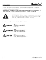
THIS SIGN SHOULD ALERT YOU: 
The Society of Automotive Engineers has adopted this Safety Alert Symbol to pinpoint characteristics that, 
if not carefully followed, can create a safety hazard. When you see this symbol in this manual or on the 
machine itself, be alert! Your personal safety and the safety of others is involved.

Defined below are the Safety Alert Messages and how they will appear in this manual:

(RED) 
Information that, if not carefully followed,  
can cause death!

(ORANGE) 
Information that, if not carefully followed, 
can cause serious personal injury or death!

(YELLOW) 
Information that, if not carefully followed,  
can cause minor injury or damage to equipment

Summary of Contents for SP-65

Page 1: ...ison Heights Michigan 48071 800 725 8377 www snowexproducts com Owner Operator s Manual SP 65 Serial PA 201033 and higher This Manual Must Be Read Before Operating The Equipment TrynEx International 2...

Page 2: ...PM EST Fax 248 691 8378 E mail customercare trynexfactory com Website www snowexproducts com General Information 3 Introduction 4 Safety 5 Operation 6 Assembly Instructions 7 10 Troubleshooting 11 War...

Page 3: ...variety of materials WARRANTY Two years parts and labor from date of installation The benefits you are about to recognize are that of time money and effort We welcome you to the world of SnowEx Perfo...

Page 4: ...d at your SnowEx Dealer THIS SIGN SHOULD ALERT YOU The Society of Automotive Engineers has adopted this Safety Alert Symbol to pinpoint characteristics that if not carefully followed can create a safe...

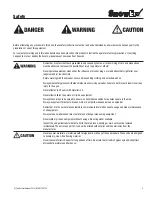
Page 5: ...is could result in serious injury to the eyes Never attempt to lift a unit with material in it Never allow children to operate or climb on equipment Always check areas to be spread to be sure no hazar...

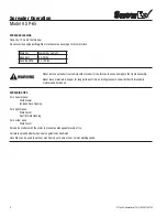
Page 6: ...s hygroscopic and will attract atmospheric moisture and harden up SPREADING TIPS For a heavier pass Walk Slower Increase Gate Opening For a lighter pass Walk Faster Restrict Gate Opening For a wider p...

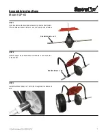
Page 7: ...Assembly Slide the Shaft Collars from the hardware kit onto the axle one on each side of the Gearbox STEP 2 Slide the Hopper Frame Assemblies over the Axle one on each side of the Gearbox STEP 3 Inst...

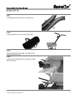
Page 8: ...stall Hopper Put Bolts with Washers through all four holes in Hopper and Frame Thread on the Nuts STEP 5 Install Frame Stand Attach to the Hopper Supports STEP 7 Put Agitator Pin through Spinner Shaft...

Page 9: ...handles at the base Hand Tighten only STEP 10 Put Handle Assembly onto frame Insert Bolts Hand Tighten STEP 11 Tighten Bolts holding the handle together then tighten the bolts holding the handle to th...

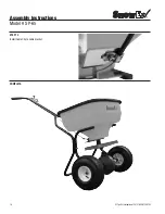
Page 10: ...TrynEx International 2013 REV B F50753 10 Assembly Instructions Model SP 65 STEP 13 Install Cable Clip to cable bracket COMPLETE...

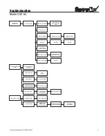
Page 11: ...ERIAL REMOVE BREAK CLUMPS AGITATOR IN PLACE BROKEN SPINNER FILL WITH MATERIAL PHYSICAL OBSTRUCTION LUBRICATE LINKAGE DRIVE WHEEL SHOULD BE ON LEFT WHEN PUSHING CABLE STUCK RECONNECT ACTUATOR LINKAGE L...

Page 12: ...ust be made to the dealer from where the product was purchased unless otherwise authorized by Snowex Snowex reserves the right to determine if any part is defective and to repair or replace such parts...

Page 13: ...ng Pin 3 16 X 1 1 4 D5923 Wheel Bushing D5926 Spinner Shaft Support D5927 Gate Adjustment Stop D5928 Gate Stop Nut D5930 Gear Cover Lock Ring D5935 Gate Stop Knob D5936 Gate Stop Spring D5938 Spring P...

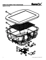
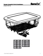
Page 14: ...TrynEx International 2013 REV B F50753 14 Hopper Assembly Parts Breakdown Model SP 65 14 13 6 11 4 8 7 10 2 9 18 12 4 5 17 15 1 3 16 14 13 6 11 4 8 7 10 2 9 18 12 4 5 17 15 1 3 16...

Page 15: ...ssembly Parts Breakdown Model SP 65 ID Part Qty 1 D5292 2 2 D5345 1 3 D5361 1 4 D5905 6 5 D5907 4 6 D5912 1 7 D5927 1 8 D5928 1 9 D5935 1 10 D5936 1 ID Part Qty 11 D5948 4 12 D5967 1 13 D5973 1 14 D59...

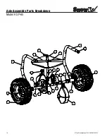
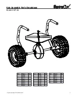
Page 16: ...national 2013 REV B F50753 16 Axle Assembly Parts Breakdown Model SP 65 8 12 9 19 7 20 17 11 14 5 18 11 11 2 10 3 8 6 21 13 18 37 1 16 15 17 4 8 12 9 20 7 21 17 11 14 5 18 11 11 2 10 3 8 6 22 13 18 19...

Page 17: ...l SP 65 ID Part Qty 1 D5902 1 2 D5909 1 3 D5910 1 4 D5911 2 5 D5913 1 6 D5915 1 7 D5919 1 8 D5921 2 ID Part Qty 9 D5923 4 10 D5926 1 11 D5930 3 12 D5938 1 13 D5939 1 14 D5941 1 15 D5947 1 16 D5956 1 I...

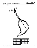
Page 18: ...TrynEx International 2013 REV B F50753 18 Handle Assembly Parts Breakdown Model SP 65 10 1 11 12 6 2 3 9 7 8 13 5 6 13 13 4 10 1 11 12 6 2 3 9 7 8 13 5 6 13 13 4...

Page 19: ...013 REV B F50753 19 Handle Assembly Parts Breakdown Model SP 65 ID Part Qty 1 D5365 2 2 D5384 1 3 D5389 1 4 D5907 2 5 D5917 2 6 D5943 5 7 D5948 2 ID Part Qty 8 D5975 1 9 D5976 1 10 D5977 1 11 D5983 1...

Page 20: ...TrynEx International 2013 REV B F50753 20 Notes...

Page 21: ...TrynEx International 2013 REV B F50753 21 Notes...

Page 22: ...TrynEx International 2013 REV B F50753 22 Notes...

Page 23: ...TrynEx International 2013 REV B F50753 23 Notes...

Page 24: ...131903...

Reviews: