background image

© Trynex International 2008      L1186

8 — 29

Troubleshooting 

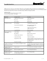
Loose electrical connections.

Blown Fuse.

Motor Seized.

Jammed auger.

Poor electrical connections.

Electrical short.

Controller failure.

Empty hopper.

Wet material.

Frozen or coarse material.

Spinner not turning.

Auger loose on shaft.

Vibrator not working.

Jammed auger, overload shut down.

Short in system.

Motor is not getting power.

Vehicle battery is extremely low,

or a poor connection exists.

 Whenever service is necessary, your local SnowEx Dealer knows your Spreader best. Take your Spreader to your local dealer for any 

maintenance or service needs on your unit. If this is not possible, the Troubleshooting Guide below may assist you in identifying the problem

Warning: 

First read all warning instructions and safety messages before servicing your spreader.

Preliminary Checks

 Be sure all electrical connections are tight and clean.

 Be sure nothing is jammed in the hopper.

Motor doesn’t run.

Controller shut down.

Material not flowing

from hopper.

Audible alarm beeping and 

display shows OL or OH.

Audible alarm beeping

display shows E1.

Audible alarm beeping

display shows EO.

Audible alarm beeping

display shows LB.

Check all connections.

Replace fuse.

Replace motor.

Carefully clear jammed material.

Clean or replace connectors.

Use dielectric grease.

Check electrical connections.

Check for bare wires.

Replace controller.

Fill hopper.

Replace with dry material.

Replace material.

Check drive assembly.

Tighten locking bolt on the side of the auger. There is a flat 

machined on the driver shaft. Align the auger with this flat 

and tighten the bolt.

Replace vibrator

Turn off for three seconds, then restart. If shut down

continues, turn off controller. Clear debris and lumps from

auger areas.

Turn off. Do not use until problem is corrected.

Turn off. Check all connections.

Turn off. Charge battery.

PROBLEM 

POSSIBLE CAUSE

SOLUTION

Summary of Contents for SP-2400

Page 1: ...Snow Ice Control FOR MODEL SP 2400 This Manual Must Be Read Before Operating The Equipment CUSTOMER COPY Warren Michigan 48089 800 725 8377 Protected by the following patents 6 089 478 6 088 865 Des...

Page 2: ...n 5 7 Spreader Assembly and Exploded Views 8 17 Wiring Instructions For Spreader Work Light 18 Electrical System Information 19 22 Spreader Mounting System 23 24 Work Light Assembly Spreader Operating...

Page 3: ...T YOU The Society of Automotive Engineers has adopted this SAFETY ALERT SYMBOL to pinpoint characteristics that if NOT carefully followed can create a safety hazard When you see this symbol in this ma...

Page 4: ...ort We welcome you to the world of Snowex Performance Registration Record the following information in this manual for quick reference Spreader Model Number ___________________________________________...

Page 5: ...children to operate or climb on equipment Always check areas to be spread to be sure no hazardous conditions or substances are in the area Always inspect unit for defects broken worn or bent parts wea...

Page 6: ...accidents are preventable and caused by human error Exercising of care and precautions must be observed to prevent the possibility of injury to operator or others Never operate equipment when under th...

Page 7: ...ons Do Not Stand On Spreader Hopper Or Frame Do Not Splice Into Electrical Harness Or Control System Inspect All Mounting Hardware After Each Use Maintain Safe Distance From Buildings Vehicles And Peo...

Page 8: ...L1186 Trynex International 2008 8 8 SP 2400 Component Assembly Views Spinner Drive Assembly Auger Drive Assembly Electrical System Assembly Hopper Assembly Frame Assembly...

Page 9: ...Trynex International 2008 L1186 8 9 SP 2400 Front and Rear Views...

Page 10: ...L1186 Trynex International 2008 8 10 SP 2400 Auger Drive Assembly Parts Breakdown...

Page 11: ...Drive Assembly Parts Breakdown Auger Drive Assembly D6584 3 8 Flange Nut D5527 1 Bearing D5702 Bearing Cover D5709 6 Variable Pitch Auger D5706 5 16 Serrated Flange Nut D6452 3 8 Serrated HHCS D6842 L...

Page 12: ...L1186 Trynex International 2008 8 12 SP 2400 Spinner Drive Assembly Parts Breakdown...

Page 13: ...4124 Spinner Mounting Hub 5 16 18 x 1 2 Hex Bolt Spinner Deflector 3 8 16 x 1 HHCS 1 4 20 x 1 2 SS HWH Serrated TCS 8 x 3 4 Self Driller HWH Spinner Drive Enclosure 5 16 Hair Pin Clip Spinner Drive Pi...

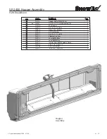
Page 14: ...L1186 Trynex International 2008 8 14 SP 2400 Hopper Assembly Parts Breakdown...

Page 15: ...D 5713 D 5714 Hopper Assembly Hopper Auger Motor Cover 1 4 20 x 1 2 SS HWH Serrated TCS RTG Hopper 3 8 16 x 2 3 4 HHCS Heavy Duty Vibrator 3 8 Flat Washer 3 8 16 x 1 1 2 HHCS Vibrator Link Arm Short...

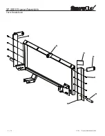
Page 16: ...L1186 Trynex International 2008 8 16 SP 2400 Frame Assembly Parts Breakdown...

Page 17: ...ty o N t r a P y e K Description 2 ea Frame Assembly D 5705 D 5736 D 5728 29 D 4122 D 5730 31 32 2400 Frame Weldment Upper Pin Bracket 1 125 1 0 3 8 16 x 1 1 2 HHCS Lower Pin 1 25 1 0 750 1 Upper Guss...

Page 18: ...customer before mounting controller some prefer not to have holes drilled into the dashboard Ty wrap loose controller harness and move to the engine compartment Do not mount close to any heater vents...

Page 19: ...N t r a P y e K 1 SP 2400 Electrical System Parts Breakdown D 5716 D 6837 D 6836 D 5708 Description Spreader Speed Control Control Power Harness Vehicle Harness Spreader Harness 1 1 1 D 6839 6 Ga Brea...

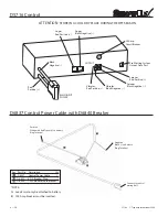
Page 20: ...tting System Output Data Port 20 Connect to control mating half Positive White with Red Tracer to battery Ring Terminal Negative Black to battery Ring Terminal NOTE A Leads must only be attached to ba...

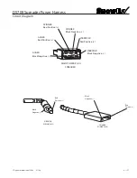
Page 21: ...Circuit Diagram AUGER Black Negative MAIN POWER PLUG SPREADER AUGER Red Positive SPINNER Red Positive SPINNER Black Negative VIBRATOR Black Negative VIBRATOR Red Positive Red Positive Black Negative...

Page 22: ...Positive AUGER Red Positive AUGER Black Negative Red Positive Black Negative Anderson Block 2 Pos Anderson Block 4 Pos VIBRATOR OUTPUT Yellow Positive VIBRATOR OUTPUT Green Negative SPINNER OUTPUT Blu...

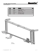
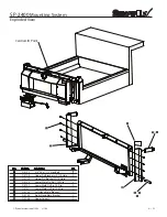
Page 23: ...4122 3 8 16 x1 1 2 Hex Bolt 8 D 5735 Right Hand Main Bracket 1 D 5728 Upper Pin Bracket w 1 125 Hole 2 D 5729 Upper Pin Bracket W 1 0 Hole 2 D 5730 Lower Weld On Pin 1 250 Dia 2 D 5731 Lower Weld On...

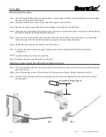
Page 24: ...eveling bracket with hair pin clip Align both rods next to each other see fig2 and weld togther Step 4 Using correct pin size provided in kit for lower latch pin measure and cut pin to correct length...

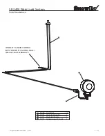
Page 25: ...400 Work Light System Parts Breakdown 8 25 CONNECT TO MAIN CONTROL INPUT POWER PLUG USING MALE FEMALE SPADE TERMINALS Key D 6784 Work Light Adapter Work Light Assembly Vehicle Harness W Switch D 5726...

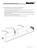
Page 26: ...Always disconnect power source before attempting toremove material baffle There are two covers provided one long and one short They can be removed in different combinations depending on the material t...

Page 27: ...ed to prevent the material from freezing SPREADING TIPS Never exceed 10 m p h when spreading For a wider pass increase spinner speed For a heavier pass drive slower or increase auger speed Never opera...

Page 28: ...r jammed auger If display reads E1 this means there is a dead short in system Do not use until problem is cor rected If display reads E 0 this means that the motor is not getting any power Check all c...

Page 29: ...re all electrical connections are tight and clean Be sure nothing is jammed in the hopper Motor doesn t run Controller shut down Material not flowing from hopper Audible alarm beeping and display show...

Page 30: ...EST TURN SHAFT BY HAND SHOULD TURN FREELY REPLACE ALL CORRODED CONNECTIONS PLUG IN SPREADER OPEN ACCESS COVER AND PLUG TOGETHER REPLACE HARNESS REPLACE ALL CORRODED CONNECTIONS TIGHTEN OR REPLACE REPL...

Page 31: ...OUCH HOPPERON 3 SIDES MATERIAL DOES NOT FLOW MATERIAL ISSUE AUGER RUNS PROPER DIRECTION AUGER RUNS BACKWARDS REPLACE VEHICLE HARNESS CHECK CONNECTIONS AT AUGER MOTOR FOR REVERSE POLARITY POLARITY CORR...

Page 32: ...When replacing parts use only original manufacturer s parts Failure to do so will void warranty Use diaelectric grease on all electrical connections to prevent corrosion at the beginning and end of t...

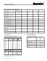
Page 33: ...refer to the Torque Chart below for the recommended fastener torque values These torque values apply to mount assembly fasteners except those noted in the instruction Recommended Fastener Torque Char...

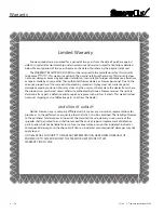
Page 34: ...e made to the dealer from where the product was purchased unless otherwise authorized by Snowex Snowex reserves the right to determine if any part is defective and to repair or replace such parts as i...

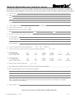
Page 35: ...s No I don t know 9 Do you feel your Trynex Dealer sold you the correct product for your needs application Yes No 10 How would you rate your overall satisfaction with your SnowEx Dealer 11 How would y...

Page 36: ...our Warranty Registration and Return It to the Factory W arm Up to with a Winter Hat F R E E F R E E 23455 REGENCY PARK DR WARREN MI 48089 2667 From Postage Required Post Office will not deliver witho...

Reviews: