© Trynex International 2008 L1186
8 — 26
Operating the Spreader
(continued)
SP-2400 INTERIOR BAFFLE & INVERTED-V INSTRUCTIONS
•
The SP-2400 uses a multi-function baffle syetm over the auger area.
.
This twin bafle design is used to reduce load on the auger drive train which controls amperage load to the electrical
system.
It must not be removed unless servicing the unit.
•
WARNING: Always disconnect power source before attempting to remove material baffle.
•
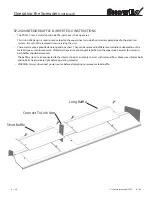
There are two covers provided one long and one short. They can be removed in different combinations depending on the
material type or moisture content. Ultimately they aid in controling material flow to the auger area, however for wet sand
both baffles should be removed.
.
The baffle system is also connected to the vibrator link arm assembly to assist with material flow. Make sure vibrator bolts
and link arm hardware are tight before operating spreader
Short Baffle
Long Baffle
Connect To Link Arm
Summary of Contents for SP-2400
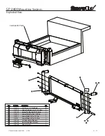
Page 9: ...Trynex International 2008 L1186 8 9 SP 2400 Front and Rear Views...
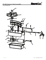
Page 10: ...L1186 Trynex International 2008 8 10 SP 2400 Auger Drive Assembly Parts Breakdown...
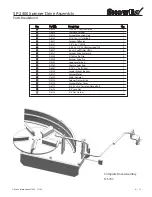
Page 12: ...L1186 Trynex International 2008 8 12 SP 2400 Spinner Drive Assembly Parts Breakdown...
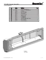
Page 14: ...L1186 Trynex International 2008 8 14 SP 2400 Hopper Assembly Parts Breakdown...
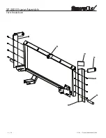
Page 16: ...L1186 Trynex International 2008 8 16 SP 2400 Frame Assembly Parts Breakdown...

