Snapper WMRP216517B Safety Instructions & Operator'S Manual Download Page 14


14 

Section 4 - ADJUSTMENTS & REPAIR 


WARNING 

DO NOT attempt any maintenance, adjustments or 
service with engine and blade running. STOP engine 
and blade. Disconnect spark plug wire and secure 
away from spark plug. Engine and components are 
HOT. Avoid serious burns, allow sufficient time for all 
components to cool. 

 
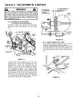
4.1.3. BLADE SHARPENING 
4.
  Sharpen blade on a grinding wheel at an angle of 
22 to 28 degrees. DO NOT sharpen blade beyond 
original cutting edge. See Figure 4.4. 


FIGURE 4.4 

 
5. Check blade for balance. If necessary, correct 
balance by grinding heavy end of blade. 
6.  Reinstall blade. See Figure 4.3. Check torque of 
blade retaining cap screw. Recommended torque 
should be  40 ft. lbs.  


NOTE: The following sections 4.2 through 
4.4 are for self-propelled models only. 

 
4.2  WHEEL DRIVE CONTROL ADJUSTMENT 

1.  The wheel drive control is properly adjusted when 
there is 1/16” to 1/8” clearance between the inside of 
the spring hook and the inside of the clutch cable 
eye with the wheel drive control released. See 
Figure 4.5. 


FIGURE 4.5 


2.  To adjust, unhook upper spring from cable eye 
and rotate spring in direction required to extend or 
shorten spring length. 
3.  Rehook upper spring to cable eye and check 
clearance. Repeat procedure if required. 

 
NOTE: The vinyl spring cover should be kept over the 
spring at all times except for adjustments. 
 

4.  If the wheel drive control fails to return quickly to 
the “OFF” position when released, check for binding 
at the cable holdings located on the side of the right 
handle. The upper clip should be located 2” below 
the upper knob; the lower clip should be 4” above 
the lower knob. The cable should slide freely with 
the clips installed at these locations.  


BLADE TIP 

DO NOT SHARPEN 
BEYOND ORIGINAL 
CUTTING EDGE 

22 TO 28º 

ORIGINAL CUTTING EDGE 

END VIEW OF 
BLADE ASSEMBLY 

CLUTCH CABLE 

VINYL SPRING COVER 

1/16” TO 1/8” 
CLEARANCE 

UPPER 
SPRING 

LOWER 
SPRING 

CLUTCH 
CABLE EYE 

SPRING HOOK 

CABLE 

CLUTCH CABLE EYE 

SPRING 

Summary of Contents for WMRP216517B

Page 1: ...wer R Recycling Model P Self Propelled Model 17 Series Designation 21 21 Cutting Width B Briggs Stratton Engine Thank you for buying a SNAPPER Product Before operating your Walk Behind read this manua...

Page 2: ...extreme CAUTION when changing directions on slopes DO NOT mow steep slopes or other areas where stability or traction is in doubt 3 Use extra care with grass catchers or other attachments these affect...

Page 3: ...rate engine in enclosed areas Engine exhaust gases contain carbon monoxide a deadly poison MAINTENANCE AND STORAGE 1 DO NOT store mower or fuel container inside where fumes may reach an open flame spa...

Page 4: ...V Belt 12 Service Annually 12 Engine 12 Air Filter 12 Engine Oil 12 Storage Procedure 12 SECTION 4 ADJUSTMENTS AND REPAIR 13 19 Mower Blade Replacement 13 Blade Sharpening 13 14 Wheel Drive Control Ad...

Page 5: ...above Figure 1 1 shows the essential parts of the SNAPPER WALK BEHIND MOWERS It is recommended that all operators of the mower become thoroughly familiar with the controls parts and operation of the...

Page 6: ...d after refueling Refer to Engine Owners Manual for specifications 2 1 6 Clean exterior surfaces of cutting deck and engine of any accumulation of spilled fuel dirt grass oil etc Keep engine air intak...

Page 7: ...r handle can be adjusted as follows 1 Loosen the lower nuts on each lower handle as shown in Figure 2 5 2 Move upper mower handle up or down until the desired position is achieved 3 Tighten the lower...

Page 8: ...eel latches to improve recycling performance INSTALLATION of GRASS BAG ADAPTER Optional Accessory on Some Models STEP 1 Install the grass bag adapter and secure to the side and top of the deck with th...

Page 9: ...ire to the grass bag Tie the bag slider to the top wire Fold bag opening into a Z and pull bag into slider See Figure 2 9 FIGURE 2 9 B Position grass bag between handles See Figure 2 10 Install grass...

Page 10: ...n and both bolts protruding through holes in the side of the deflector Secure nuts to the side of deflector Tighten nuts securely See Figure 2 13 FIGURE 2 13 2 9 INSTALLATION of RECYCLING COVER Option...

Page 11: ...s are HOT Avoid serious burns allow sufficient time for all components to cool 1 Refer to Engine Manual for proper oil specifications and procedures 2 For simplest cleanest oil change loosen lower han...

Page 12: ...evered or belt strands exposed If worn or damaged replace belt before operating mower 3 2 5 CHECK TRANSMISSION POLY V BELT 1 Visually check poly v belt for cracking fraying severed or belt strands exp...

Page 13: ...either tip See Figure 4 1 4 2 Replace with new blade WARNING DO NOT use a cutting blade that shows signs of excessive wear or damage Refer to Section MOWER BLADE REPLACEMENT for proper blade inspecti...

Page 14: ...1 8 clearance between the inside of the spring hook and the inside of the clutch cable eye with the wheel drive control released See Figure 4 5 FIGURE 4 5 2 To adjust unhook upper spring from cable e...

Page 15: ...s causing slippage clean discs as follows 1 Wipe away any oil or grease with a clean cloth 2 Use either an approved grease solvent or hot soapy water to clean drive disc or driven disc 3 Rinse compone...

Page 16: ...ewed from operators position Then retighten the connector hex nut securely See Figure 4 10 Move ground speed control to the first speed position then back to the sixth speed position Recheck the 1 8 m...

Page 17: ...MPORTANT The bearing on these M series machines is staked into the thrust plate The bearing will have to be driven out with a mallet and a large punch A new bearing with four retaining screws will hav...

Page 18: ...earing 5 Carefully install new O ring over the outside of the new bearing 6 Install bearing holder and secure with screws 7 Install 3 8 hex lock nut FIGURE 4 14 4 4 BELT SERVICE On self propelled mowe...

Page 19: ...ck washer See Figure 4 16 6 Remove the belt cover located under deck 7 Lift the drive disc up and remove worn belt 8 Loop one end of new belt over engine pulley and insert the other end through slot i...

Page 20: ...f Traction 2 Engine drive belt broken requires replacement 2 Replace engine drive belt 3 Engine drive belt has jumped off of the pulley 3 Reinstall belt onto pulley Check for damage Self Propelled Mod...

Page 21: ...wer Deck Clean Debris Accumulation Page 10 X Transmission Grease Check Grease Level Pages 9 X X Periodic Grease Check Pages 10 X Drive Disc Check for Wear Damage Replacement Page 12 15 X Change oil ev...

Page 22: ...ginal purchase date SNAPPER will not be responsible for any installation cost incurred The battery warranty only covers original equipment batteries and does not cover damage to the battery or machine...

Page 23: ...23 PRIMARY MAINTENANCE...

Page 24: ...24 PRIMARY MAINTENANCE...

Page 25: ...25 PRIMARY MAINTENANCE...

Page 26: ...26 PRIMARY MAINTENANCE...

Page 27: ...one Number____________________________________________________ It is very important that you register your purchase with Snapper to ensure warranty coverage Please mail your product registration card...

Page 28: ...s If you have any questions about your Snapper product contact your local authorized Snapper dealer or contact Snapper Customer Service at Snapper McDonough GA 30253 Phone 1 800 935 2967 COPYRIGHT 200...

Reviews: