Snapper Simplicity 2690476 Operator'S Manual Download Page 24

C

B

23

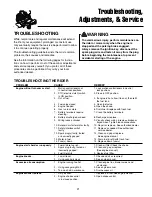
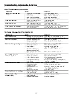
Troubleshooting, Adjustments, & Service

SEAT ADJUSTMENTS

The seat and motion control levers should be adjusted so
that operator’s elbows are supported by the arm rests
when his/her hands are on the controls, and the motion
control levers can be moved through their full range of
motion without contacting the operator’s legs.

Seat Position Adjustment

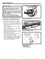
See Figure 20. The seat can be adjusted forward and
back. Remove the knobs (A), and loosen the support
bolts (B). Slide the seat to the desired position, then
reinstall the knobs and retighten the bolts.

MOTION CONTROL LEVER
ADJUSTMENT

The motion control levers can be adjusted in two ways.
The placement of the levers (how close the ends are to
one another) and the height of the levers can be adjust-
ed.

To Adjust the Lever Placement:

Loosen the two bolts

(B, Figure 21) securing the control track, and adjust the
control track in or out to properly adjust the lever end
spacing.

Note: The bottom bolt may be accessed from beneath
the fender.

To Adjust the Handle Height:

Remove the motion con-

trol lever mounting hardware (A, Figure 21) and reposi-
tion the lever either up or down from its original position.
You may need to readjust the handle placement as
described above.

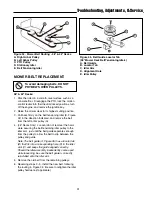
Figure 20. Seat Adjustment
A. Adjustment Knobs
B. Support bolts

Figure 21. Motion Control Lever Adjustments
A. Lever Height Adjustment Hardware
B. Lever Placement Adjustment Hardware
C. Forward Adjust Plate

A

B

SPEED BALANCING ADJUSTMENT

If the rider veers to the right or left when the motion con-
trol levers are in the maximum forward position, the top
speed of each of these levers can be balanced. Only
adjust the speed of the wheel that is traveling faster.

TO REDUCE THE SPEED OF THE FASTER WHEEL

1. Loosen the two bolts securing the forward adjust

plate (C, Figure 21).

2. Slide the plate up approximately 1/8”.

3. Retighten the bolts and recheck speed balance.

4. Repeat steps 1-3 until adjustment is complete.

WARNING

DO NOT adjust the rider for a faster overall speed
forward or reverse than it was designed for.

A

Summary of Contents for Simplicity 2690476

Page 1: ...T185380BVE 18 5HP Zero Turn Rider with 38 Mower 7800010 RZT20420BVE2 20HP Zero Turn Rider with 42 Mower Javelin Series Simplicity Mfg No Description 2690476 RZT20380KH 20HP Zero Turn Rider with 38 Mow...

Page 2: ...rating instructions can result in loss of machine control serious personal injury to you and or bystanders and risk of equipment and property damage The triangle in the text signifies important cautio...

Page 3: ...stability of the machine 1 DO NOT operate machine on slopes exceeding 15 degrees 27 grade 2 Exercise EXTREME CAUTION on slopes above 10 degrees 18 grade Turn blades OFF when traveling uphill Use a sl...

Page 4: ...ange clothing immediately 11 Never overfill a fuel tank Replace fuel cap and tighten securely OPERATION 1 Mount and dismount machine from left side Keep clear of discharge opening at all times 2 Start...

Page 5: ...rovide adequate ventilation when running engine Exhaust gases contain carbon monoxide an odorless and deadly poison 7 Disconnect negative black cable from battery before per forming maintenance or ser...

Page 6: ...n be found in the locations shown NOTE For location of engine identification numbers refer to the engine owner s manual S S A A M M P P L L E E S S A A M M P P L L E E Snapper Models Simplicity Models...

Page 7: ...ld be carefully read and obeyed Personal bodily injury can result when these instructions are not followed The information is for your safety and it is important The safety decals below are on your ri...

Page 8: ...n control levers not locked in their neutral locked positions OR With operator seated right motion control lever is moved out of its neutral locked position before left motion control lever TEST 4 BLA...

Page 9: ...eed Control The engine speed control controls engine speed Move the engine speed control forward to increase engine speed and back to decrease engine speed Always operate at FULL engine speed Choke Cl...

Page 10: ...O to function Transmission Release Valves The transmission release valves deactivate the transmis sions so that the unit can be pushed by hand See PUSHING THE UNIT BY HAND for operational informa tion...

Page 11: ...ever allow passengers to ride on the unit Before leaving the operator s position for any reason lock the motion control levers in the neutral locked position disengage the PTO stop the engine and remo...

Page 12: ...tart the engine see STARTING THE ENGINE 3 Set the mower cutting height see CUTTING HEIGHT ADJUSTMENT 4 Set the engine speed control to FULL 5 Engage the PTO by pulling up on the switch 6 Move the moti...

Page 13: ...Travel Practice Gradually move both motion control levers evenly FORWARD from neutral Slow down and repeat NOTE Straight forward travel takes practice If neces sary top speed can be balance adjusted...

Page 14: ...ri enced with operating the zero turn rider you will learn more maneuvers that will make your mowing time easier and more enjoyable Remember the more you practice the bet ter your control of the rider...

Page 15: ...Arbor Blade Spindle Pulley B Stationary Idler C PTO Pulley D Tensioning Idler A C D B Figure 9 Trailer Weight Recommendations A Clevis Pin B Clip A B ATTACHING A TRAILER The maximum weight of a towed...

Page 16: ...tion See CUTTING HEIGHT ADJUSTMENT 3 Pivot the front wheels out of the way and slide the mower deck under the unit Place a 2 x 4 or similar support under the mower deck 4 Hook the front hanger bar A F...

Page 17: ...s Every 25 Hours Every 100 Hours Every 250 Hours Spring Fall Check Rider Mower for loose hardware Check Clean Engine Cooling Fins Check Adjust PTO Clutch Lubricate Rider Mower Clean Battery Cables Che...

Page 18: ...at the points shown in Figure 13 as well as the others listed in this section Grease front caster wheel axles front caster spindle bosses front axle center pivot mower deck arbors blade spindles mower...

Page 19: ...tall the blade Figure 16 with the tabs pointing up toward the mower deck as shown 7 Reinstall the blade washers B Figure 16 concave side up and capscrew or nut C Use a wooden block A to prevent blade...

Page 20: ...r B Figure 18 5 Remove hoses from filter 6 Install new filter in proper flow direction in fuel line 7 Secure with hose clamps 8 Reconnect the negative battery cable when finished ENGINE MAINTENANCE Re...

Page 21: ...an enclosed struc ture see warning Battery life will be increased if it is removed put in a cool dry place and fully charged about once a month If the battery is left in the unit disconnect the negati...

Page 22: ...fill the fuel tank 4 Fuel valve closed 4 Open fuel valve 5 Engine flooded 5 Open the choke 6 Gas is old or stale 6 Drain fuel replace with fresh fuel 7 Battery terminals require 7 Clean the battery te...

Page 23: ...cut is rough looking 1 Engine speed too slow 1 Set engine speed control to full 2 Ground speed too fast 2 Decrease Ground Speed 3 Blades are dull 3 Sharpen or replace blades See Mower Blade Service 4...

Page 24: ...end spacing Note The bottom bolt may be accessed from beneath the fender To Adjust the Handle Height Remove the motion con trol lever mounting hardware A Figure 21 and reposi tion the lever either up...

Page 25: ...e ground will damage turf and or unit MOTION CONTROL LEVER FRICTION ADJUSTMENT The motion control levers should be tight when moving in and out of their neutral locked positions If the levers are loos...

Page 26: ...od end jam nut B If the transmission is creeping forward turn the rod end in clockwise one or two turns to shorten the link rod E If the transmission is creeping in reverse turn the rod end out counte...

Page 27: ...on control levers moved from their neutral locked positions measure the length of the compression spring F The measurement should be between 2 1 2 and 2 3 4 If not tighten or loosen the brake rod adju...

Page 28: ...ent nuts B Figure 25 until the rotor face and armature face just contacts the gauge 5 Check the windows for an equal amount of tension when the gauge is inserted and removed and make any necessary adj...

Page 29: ...3mm If there is more than 1 8 3mm difference between the measurements on each side proceed to step 5 If the difference is 1 8 3mm or less proceed to step 6 5 Use the rear leveling nuts B Figure 29 to...

Page 30: ...ifference between the measurements on each side proceed to step 5 5 Locate the roller bar leveling hardware on the right side of the mower deck A Figure 32 Loosen the hardware and raise or lower the r...

Page 31: ...Y CHARGING A dead battery or one too weak to start the engine may be the result of a defect in the charging system or other electrical component If there is any doubt about the cause of the problem se...

Page 32: ...te The belt guide A Figure 35 has a locator tab B that fits into a corresponding hole D in the idler arm C and keeps the guide aligned correctly Should the idler assembly inadvertently come apart whil...

Page 33: ...nd remove the ignition key 2 Raise the seat The fuse holders are located on the right side of the rear seat support 3 Remove and check the suspected fuse or fuses If blown replace with a fuse with a r...

Page 34: ...38 Mower Deck 49 124 5 cm With 42 Mower Deck 52 132 1 cm Height 38 96 5 cm Weight apx With 38 Mower Deck Simplicity 520 lbs 236 kg With 38 Mower Deck Snapper 500 lbs 227 kg With 42 Mower Deck 540 lbs...

Page 35: ...notes and and torque values are also included For applicable manuals currently available for your model contact our Customer Publications Department at 262 284 8519 Have the information listed in the...

Page 36: ...INC 500 N Spring Street PO Box 997 Port Washington WI 53074 0997 www simplicitymfg com Copyright 2006 Simplicity Manufacturing Inc All Rights Reserved Printed in USA PRODUCTS INC McDonough GA 30253 ww...

Reviews: