


30
Section 4 - ADJUSTMENT & REPAIR
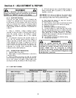
4.5 BATTERY
4.5.1. BATTERY
REMOVAL
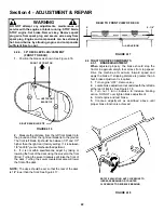
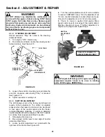
1. Raise operator's seat.
2. Remove the two adjusting knobs.
3. Remove seat assembly and move forward. Use
care not to disconnect wires from seat switch. See
Figure 4.41.
FIGURE 4.41
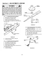
4. Remove negative ( - ) cable first.
5. Remove positive ( + ) cable last.
6. Remove battery. See Figure 4.42.
WARNING
Cables must be connected to battery terminals in the
proper position as shown in Figure 4.42. DO NOT
attempt to charge battery while installed on tractor.
DO NOT use "BOOST" chargers on the battery.
FIGURE 4.42
4.5.2. BATTERY
INSTALLATION
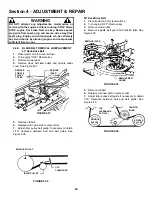
1. Slide battery into battery housing.
2. Connect positive (+) cable first.
3. Connect negative (-) cable last.
4. Reinstall seat assembly. Use care not to
disconnect wires from seat switch.
5. Reinstall the two adjusting knobs.
6. Lower operator's seat.
WARNING
The electrolyte (acid) produces a highly explosive
gas. Keep all sparks, flame and fire away from area
when charging battery or when handling electrolyte
or battery. Electrolyte (acid) is a highly corrosive
liquid. Wear eye protection. Wash affected areas
immediately after having eye or skin contact with
electrolyte (acid). Battery acid is corrosive. Rinse
empty acid containers with water and mutilate before
discarding. If acid is spilled on battery, bench, or
clothing, etc., Flush with clear water and neutralize
with baking soda.
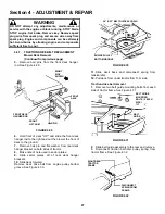
4.5.3. BATTERY
SERVICE
1. Remove battery. See Section on Battery Removal.
2. Place battery in a well ventilated area on a level
surface.
3. Using distilled water, refill cells as required to
cover cell plates of which can also be visualized
through the plastic battery case.
4. With cell caps removed, connect battery charger
to battery terminals. Red to positive (+) terminal and
black to negative (-) terminal.
5. Slow charge battery at 1 amp for 10 hours.
6. If battery will not accept charge or is partially
charged after 10 hours of charging at 1 amp, replace
with new battery.
4.5.4. BATTERY
STORAGE
When out of season, it is recommended the battery
be removed, charged and stored.
1. Remove battery. (Refer to Section “BATTERY
REMOVAL”).
2. Perform battery service.
3. Bring battery to full charge, if required.
4. Store battery in an area away from the RIDER on a
wood surface. DO NOT STORE BATTERY ON A
CONCRETE SURFACE.
WARNING
DO NOT attempt to charge battery while installed on the
machine. DO NOT use “BOOST” chargers on the
battery. DO NOT OVERFILL!
REMOVE ADJUSTING
KNOBS AND MOVE
SEAT FORWARD
REMOVE POSITIVE
(+) CABLE LAST
REMOVE NEGATIVE (-)
CABLE FIRST
Summary of Contents for LT145H33GBV
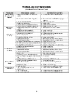
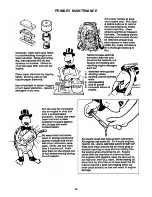
Page 38: ...38 PRIMARY MAINTENANCE...
Page 39: ...39 PRIMARY MAINTENANCE...
Page 40: ...40 PRIMARY MAINTENANCE...
Page 41: ...41 PRIMARY MAINTENANCE...