background image


25


NOTES 

___________________________________________________________________  
___________________________________________________________________  
___________________________________________________________________  
___________________________________________________________________  
___________________________________________________________________  
___________________________________________________________________  
___________________________________________________________________  
___________________________________________________________________  
___________________________________________________________________  
___________________________________________________________________  
___________________________________________________________________  
___________________________________________________________________  
___________________________________________________________________  
___________________________________________________________________  
___________________________________________________________________  
___________________________________________________________________  
___________________________________________________________________  
___________________________________________________________________  
___________________________________________________________________  
___________________________________________________________________  
___________________________________________________________________  
___________________________________________________________________  
___________________________________________________________________  
___________________________________________________________________  
___________________________________________________________________  
___________________________________________________________________  
___________________________________________________________________  
___________________________________________________________________  
___________________________________________________________________  
___________________________________________________________________  
___________________________________________________________________  
___________________________________________________________________  
___________________________________________________________________  
___________________________________________________________________  
___________________________________________________________________  
___________________________________________________________________  
___________________________________________________________________  
___________________________________________________________________  
___________________________________________________________________  
___________________________________________________________________  
___________________________________________________________________  


33

Summary of Contents for ESZT18336BVE

Page 1: ...r buying a SNAPPER Product Before operating your SCRAMBLER read this manual carefully and pay particular attention to the IMPORTANT SAFETY INSTRUCTIONS on Pages 2 4 Remember that all power equipment c...

Page 2: ...achine 1 DO NOT operate machine on slopes exceeding 15 degrees 27 grade 2 Exercise EXTREME CAUTION on slopes above 10 degrees 18 grade Turn blades OFF when traveling uphill Use a slow speed and avoid...

Page 3: ...of the fuel tank or container opening at all times until fueling is complete DO NOT use a nozzle lock open device 10 If fuel is spilled on clothing change clothing immediately 11 Never overfill a fue...

Page 4: ...l bolts nuts and screws properly tight Check that all cotter pins are in proper position 6 Always provide adequate ventilation when running engine Exhaust gases contain carbon monoxide an odorless and...

Page 5: ...el Filter 17 Storage Out of Season 17 SECTION 4 ADJUSTMENTS AND REPAIR 18 26 Motion Control Adjustments 18 Engine Adjustments Repair 19 Mower Deck Component Adjustments 19 24 Mower Drive Belt Adjustme...

Page 6: ...l operators of this equipment become thoroughly familiar with the controls components and operation of this machine before operating Specific details involving the engine are found in the separate eng...

Page 7: ...TION CONTROL LEVERS Controls direction and steering of machine when driving Refer to Section MOTION CONTROL for detailed operation of motion control levers FIGURE 1 5 Levers shown in Neutral Lock Posi...

Page 8: ...ERATION 2 2 1 STARTING ENGINE 1 Make sure both motion control levers are lifted fully up and out into their neutral lock positions See Figure 1 5 2 Make sure blade switch is pushed in to its off 0 pos...

Page 9: ...nter of the machine and rest elbows comfortably on armrests See Figure 2 3 FIGURE 2 3 2 3 2 FORWARD MOTION Slowly and equally push both levers forward See Figure 2 4 The farther you push the faster th...

Page 10: ...6 STOPPING MOTION 1 Return both motion control levers to neutral 2 If driving is not to be resumed immediately lift levers fully up and out into their neutral lock positions and engage parking brake I...

Page 11: ...detent or choke will engage and engine will stall 2 Pull Blade Switch out to its on I position to engage mower blade See Figure 2 10 2 4 2 MOWING OPERATIONS 1 Please refer to the Important Safety Ins...

Page 12: ...r neutral lock positions ENGINE SHOULD START IF 1 Park Brake is engaged AND 2 Blade Switch is pushed in to its off 0 position AND 3 Motion Control Levers are in their neutral lock positions ENGINE MUS...

Page 13: ...ay have spilled Dispose of drained oil properly See Figure 3 1 7 Change oil filter at every oil change Refer to your engine owner s manual for service instructions 8 Fill engine crankcase with new oil...

Page 14: ...3 2 4 CHECK TRANSAXLE DRIVE BELTS 1 Checking Transaxle Belt Tension The transaxle drive belt requires no adjustment If belt is frayed slit severed or belt strands exposed replace belt before operatin...

Page 15: ...en turned off Refer to Section BLADE BRAKE ADJUSTMENT 2 Mower Drive Belt Check belt for proper tension No adjustment required Replace belt as needed 3 Mower Blade Check blade for sharpness wear damage...

Page 16: ...ll have to be removed to lubricate the pivot shaft The access hole is at the rear of the front structure underneath the footrest a The pivot shaft grease fitting can be accessed through a hole at the...

Page 17: ...e SCRAMBLER immediately to the nearest authorized Snapper dealer for service 3 4 6 Fuel Filter Service fuel filter as instructed below Close fuel valve in fuel line Run engine until engine runs out of...

Page 18: ...e motion control levers are released return springs assist them back to the neutral position See Figure 4 1a To adjust spring tension 1 If a stronger return is desired tighten the nyloc nut atop the r...

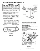
Page 19: ...made by an authorized SNAPPER dealer 4 3 1 MOWER DRIVE BELT ADJUSTMENT The 33 and 38 mower deck drive belts do not require any adjustment If the belt does not drive blade properly replace belt as nee...

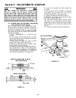
Page 20: ...blade rotation in 5 seconds or less after being turned off If blades continue to rotate longer than 5 seconds adjustment or replacement is required When properly adjusted a 010 to 012 feeler gauge wil...

Page 21: ...een the blade tip and deck lip should be 3 8 See Figure 4 6 9 Repeat step 8 with blade tip B 10 If measurement between blade tips and deck are different and there is more than 1 16 difference between...

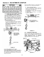
Page 22: ...ece of angle iron pipe or similar object under center of deck at the rear 4 Remove rear hanger chains and allow center rear of deck to rest on angle iron 5 Measure the distance from blade tips to floo...

Page 23: ...n 4 Repeat steps a through c until proper levelness is obtained FIGURE 4 11 Front to Rear Deck Pitch 38 Decks With the SCRAMBLER on a smooth level surface rotate blades until blade tips are at front a...

Page 24: ...or damage See Figure 4 15 FIGURE 4 15 4 5 2 BLADE SHARPENING 1 Close vent in fuel cap and make sure cap is tight See Figure 2 2 2 Remove key from ignition switch Engage parking brake 3 Remove spark pl...

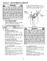
Page 25: ...4 6 3 BATTERY SERVICE 1 Remove battery Refer to Section BATTERY REMOVAL 2 Place battery in a well ventilated area on a level surface 3 Using distilled water refill cells as required to cover cell plat...

Page 26: ...to 80 charged state 4 With cell caps removed connect battery charger to battery terminals RED to positive and BLACK to negative terminal WARNING DO NOT OVERFILL DO NOT attempt to charge battery while...

Page 27: ...e park brake Applicable models 3 Motion Control Levers not in neutral lock position 3 Lift levers into neutral lock position 4 Fuel tank empty or fuel shut off valve closed 4 Fill fuel tank with fresh...

Page 28: ...re 1 Bring to proper pressure Improperly 2 Cutting height too low or high 2 Adjust cutting height 3 Engine speed too slow 3 Move engine speed control to FAST position 4 Forward speed too fast 4 Move j...

Page 29: ...s Check For Wear And Tension Page 19 20 X X X Mower Blades Check For Wear Damage Replacement Pages 24 25 X Mower Deck Clean Debris Accumulation Page 15 X Mower Deck Clean Outside and Underside Page 15...

Page 30: ...ut entire Grass Catcher or Guard in place STOP ENGINE AND REMOVE KEY BEFORE PERFORMING MAINTENANCE KEEP CHILDREN AND OTHERS OUT OF MOWING AREA DANGER FLYING MATERIAL DO NOT MOW IN REVERSE WATCH FOR CH...

Page 31: ...AKE ENGAGE PARKING BRAKE Indicates direction in which parking brake is engaged 7 EUROPEAN CERTIFICATION REAR OF MACHINE Indicates certification by the European Community 8 NOISE CONTROL REAR OF MACHIN...

Page 32: ...nal purchase date SNAPPER will not be responsible for any installation cost incurred The battery warranty only covers original equipment batteries and does not cover damage to the battery or machine c...

Page 33: ...___________________________________________________________________ ___________________________________________________________________ _______________________________________________________________...

Page 34: ...___________________________________________________________________ ___________________________________________________________________ _______________________________________________________________...

Page 35: ...__________________________________ ___________________________________________________________________ ___________________________________________________________________ _____________________________...

Page 36: ...any questions about your Snapper product contact your local authorized Snapper dealer or contact Snapper Customer Service at Snapper McDonough GA 30253 Phone 1 800 935 2967 COPYRIGHT 2004 SNAPPER A D...

Reviews: