background image


TABLE OF CONTENTS 


IMPORTANT SAFETY INSTRUCTIONS ............ 2-3 
 
TABLE OF CONTENTS ........................................ 4 
 
SECTION 1 - FAMILIARIZATION ...................... 5-7 

 Components ........................................................5 
 Controls ................................................................5 
 

Decals / Symbols ............................................. 6-7 

 
SECTION 2 -  
OPERATING INSTRUCTIONS ........................ 8-12 

 Pre-start 

Checklist 

..............................................8 


Operator’s Seat Adjustment  ..............................8 


Starting & Stopping Engine .......................... 9-10 


Starting & Stopping Wheel Drive .....................10 


Starting & Stopping Mower Blades............ 10-11 

 Parking 

Brake.....................................................11 

 Cutting 

Height 

Adjustment ...............................11 


Rolling Tractor With Engine Off .......................12 


Reverse Lockout Mechanism ...........................13 

 
SECTION 3 -  
MAINTENANCE INSTRUCTIONS ................. 14-18 


Service - After First 5 Hours .............................14 


Change Engine Oil .............................................14 


Check Blade Brake ............................................14 


Check Mower Blade...........................................14 


Check Deck Drive Belt.......................................15 


Service – Every 25 Operating Hours ................15 

 Check 

Engine ..................................................15 

 Mower 

Components .......................................15 


Check Blade Brake .........................................15 

 Lubrication 

(Tractor) ................................... 16-17 


Front Wheel Bearings ....................................16 

 Axle 

Spindles ..................................................16 

 Clutch/Brake 

Pivot..........................................16 


Steering Sector Gear ......................................16 

 Steering 

Shaft .................................................16 


Steering Drag Link..........................................16 


Steering Tie Rod .............................................17 


Blade Engagement Mechanism.....................17 


Park Brake Lever ............................................17 


Deck Lift Mechanism......................................17 


Service - Annually ........................................ 17-18 

 Engine..............................................................17 
 Fuel 

Filter................................................... 17-18 

 Spark 

Plug .......................................................18 


Hydrostatic Transmission Oil........................18 


SECTION 4 -  
ADJUSTMENTS & REPAIR........................... 19-30 


Engine Adjustments & Repair .......................... 19 


Mower Deck & Component Adjustments ........ 19 


Blade Brake Adjustment ................................... 19 


33” Deck Blade Brake Adjustment................... 19 


Blade Belt Adjustment .................................19-20 


Adjusting Mower Blade ...............................20-21 


33” Side To Side ...........................................21-22 


   (Deck Level Adjustment) 


33” Front To Rear Sector Plates ...................... 22 


   (Deck Level Adjustment) 


33” Front To Rear Front Lift Rod ..................... 22 


   (Deck Level Adjustment) 


Brake Adjustment - HYDRO DRIVE.................. 23 

 Steering 

Adjustment ......................................... 23 

 Shifter 

Adjustment .......................................23-24 


Traction Drive Belt Adjustment........................ 24 


Mower Blade Service ...................................24-25 


Mower Blade Sharpening .............................. 25 


Mower Blade Replacement.......................25-26 


Traction Drive Belt Removal/Replace.........26-28 


Deck Belt Removal & Replacement ................. 28 

 Battery 

Service .............................................29-30 


AVAILABLE ACCESSORIES

.................................. 31 


SECTION 5 -  
ELECTRICAL SYSTEM ................................. 32-33 

 Harness 

Routing................................................ 32 


Schematics - Briggs & Stratton w/Lights........ 33 

 
TROUBLESHOOTING GUIDE ................................34-35 
 
MAINTENANCE SCHEDULE ....................................... 36 
 
MAINTENANCE PARTS............................................... 36 
 
WARRANTY.................................................................. 37 


IMPORTANT 

The figures and illustrations in this manual are 
provided for reference only and may differ from 
your specific model. Contact your Snapper dealer 
if you have questions. 

Summary of Contents for ELT150H33IBV

Page 1: ...ngine Horse Power B Briggs Stratton Engine H Hydrostatic Transmission V Over Head Valve Type Engine Thank you for buying a SNAPPER product Before operating the Lawn Tractor read and follow the IMPORTA...

Page 2: ...e machine 1 DO NOT operate machine on slopes exceeding 10 degrees 27 grade 2 Exercise EXTREME CAUTION on ALL slopes Turn blades OFF when traveling uphill Use a slow speed and avoid sudden or sharp tur...

Page 3: ...light 13 Move joystick if equipped SLOWLY to maintain control during speed and directional changes OPERATION Continued From Previous Column 14 Exercise CAUTION when pulling loads Limit loads to those...

Page 4: ...7 Service Annually 17 18 Engine 17 Fuel Filter 17 18 Spark Plug 18 Hydrostatic Transmission Oil 18 SECTION 4 ADJUSTMENTS REPAIR 19 30 Engine Adjustments Repair 19 Mower Deck Component Adjustments 19 B...

Page 5: ...perator s Manual and Engine Owner s Manual before operating this machine Keep these manuals available for future reference CONTROLS All operators should be acquainted with the operator s controls befo...

Page 6: ...an authorized SNAPPER dealer should be contacted for explanation ROLL RELEASE DECAL 7 2749 OUT TO ROLL IN TO DRIVE PATENT NUMBERS DECAL 2 9470 CHUTE WARNING DECAL 2 9784 SERIAL NUMBER DECAL 0 1015 EU...

Page 7: ...STRUCTIONS CONTROL IDENTIFICATION 7 2754 FORWARD REVERSE NEUTRAL DIRECTION AND SPEED CONTROL 7 3424 HEIGHT OF CUT DECAL 4 6218 LOWEST HEIGHT OF CUT HIGHEST HEIGHT OF CUT CONSOLE DECAL 7 3579 RABBIT FA...

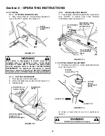
Page 8: ...ngine and tractor of any accumulation of dirt grass oil etc Keep engine air intake screens and cooling fins clean at all times 2 1 6 With engine OFF move the tractor outside and add fuel to the fuel t...

Page 9: ...ails to work DO NOT OPERATE the tractor until the interlock has been repaired FIGURE 2 5 5 Choke engine for cold starting by moving engine speed control to CHOKE position Little or no choking will be...

Page 10: ...o ON See Figure 2 8 FIGURE 2 8 WARNING DO NOT operate blades in reverse STOP BLADES LOOK and SEE behind and down for children pets and hazards before and while backing 2 4 STOPPING ENGINE BLADE WHEEL...

Page 11: ...s clutch brake pedal 2 Move park brake lever up into slot See Figure 2 12 3 Release pedal FIGURE 2 12 2 4 5 RELEASING PARK BRAKE 1 Fully depress clutch brake pedal Move park brake lever DOWN to releas...

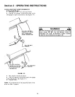
Page 12: ...engage hydro transmission See Figure 2 15 5 Set park brake NOTE The transmission will not propel the tractor if it is left in the ROLL position WARNING DO NOT disengage the hydro transmission and coa...

Page 13: ...verse operation until the blade engagement lever is moved to the OFF position at which time the system will return to its Reverse Lockout mode This feature should never be selected unless you are abso...

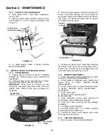
Page 14: ...beneath end of oil drain 3 After all oil has drained push drain body IN and rotate clockwise to close 4 Fill engine with new motor oil as specified in engine owner s manual WARNING The following proce...

Page 15: ...air cleaner per engine owner s manual FIGURE 3 5 3 Reinstall air cleaner cover Insert tabs located at the bottom of the cover into corresponding slots in engine cover Position cover and engage latch...

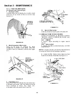
Page 16: ...vot The clutch brake pivot is located on the L H underside of the tractor and is lubricated with one shot of general purpose grease See Figure 3 7 FIGURE 3 7 4 Steering Sector Gear Lubricate with a li...

Page 17: ...motor oil FIGURE 3 12 10 Deck Lift Mechanism Lubricate all wear and pivot points of the deck lift 3 4 ANNUALLY END OF EACH SEASON Perform all maintenance as described in Section SERVICE EVERY 25 OPER...

Page 18: ...h fresh gasoline Refer to engine owner s manual for fuel specifications 3 4 3 SPARK PLUG Remove and replace engine spark plug Refer to engine owner s manual for correct replacement plug and gap specif...

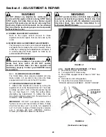
Page 19: ...when the blade engagement lever is moved to the OFF position 33 DECK BLADE BRAKE ADJUSTMENT 1 Blade brake adjustment is made by turning the adjustment nut on the threaded brake rod The brake is initi...

Page 20: ...after performing blade belt adjustment 11 Check blade brake Refer to Section CHECK BLADE BRAKE Blades must stop rotating in 5 seconds or less when turned off 4 2 3 ADJUSTING MOWER BLADE 33 Decks Only...

Page 21: ...ne OFF Remove key 3 Place a piece of angle iron under center rear of deck 4 Remove hair pins and washers securing rear of deck to sector plates See Figure 4 7 5 Slide sector off of pins and carefully...

Page 22: ...L ADJUSTMENT FRONT TO REAR FRONT LIFT ROD If the sector plates are in their lowest setting and proper level cannot be obtained adjust the front lift rod as follows 1 Move deck lift lever to 5 position...

Page 23: ...e eccentric clockwise until steering Play is reduced Refer back to Figure 4 14 4 Tighten eccentric mounting nut 4 3 3 SHIFTER ADJUSTMENT The shift linkage is set at the factory and should not require...

Page 24: ...owards right side of tractor for more belt tension NOTE Note the orientation of belt guide and make certain it remains in the same orientation after moving idler NOTE Should less tension be required m...

Page 25: ...to a firm level surface 2 Turn engine OFF Remove key 3 Remove mowing deck from tractor 4 Remove mower blade s 5 Sharpen all cutting edges of the Ninja recycling blade at an angle of 22 to 28 degrees...

Page 26: ...components sufficient time to cool 4 4 6 TRACTION DRIVE BELT REPLACEMENT Mower Deck Removal 5 Remove hair pins from the front deck hanger rod See Figure 4 23 6 Hold front of deck UP and slide the fron...

Page 27: ...re the traction drive belt idler tension pulley and stationary idler pulleys See Figure 4 27 VIEW FROM UNDERNEATH TRACTOR FIGURE 4 27 5 Remove traction drive belt from engine pulley top groove See Fig...

Page 28: ...ark plug and secure wire away from spark plug Engine and components can be extremely hot Avoid burns by allowing engine and components sufficient time to cool 4 4 7 DECK BELT REMOVAL REPLACEMENT 33 De...

Page 29: ...yte acid Battery acid is corrosive Rinse empty acid containers with water and mutilate before discarding If acid is spilled on battery bench or clothing etc Flush with clear water and neutralize with...

Page 30: ...to 80 charged state 4 With cell caps removed connect battery charger to battery terminals RED to positive and BLACK to negative terminal IMPORTANT 3 16 above cell plates is the recommended level DO N...

Page 31: ...1914 Lawn Sweeper 6 1913 Aerator 6 1911 Broadcast Spreader 6 1916 Lawn Roller 6 1915 42 Snow Blade 6 1352 44 Dozer Blade Spring Trip 6 1881 Dozer Blade Support Kit 6 1370 40 Snow Thrower 6 1880 Debris...

Page 32: ...ting various electrical components FIGURE 5 1 TO BATTERY NEGATIVE TERMINAL TO BATTERY POSITIVE TERMINAL SOLENOID UNDER SEAT SEAT SWITCH IGNITION SWITCH HEADLIGHT SWITCH 20 AMP FUSE PARK BRAKE SWITCH T...

Page 33: ...34 SECTION 5 ELECTRICAL SYSTEM SCHEMATICS BRIGGS STRATTON WITH LIGHTS FIGURE 5 2...

Page 34: ...position 2 Move engine speed control to FAST 3 Fuel tank empty 3 Fill with fuel to proper level 4 Engine air pre cleaner and or air cleaner dirty 4 Clean free of all debris 5 Spark plug defective or...

Page 35: ...rd speed too fast 4 Move speed control to a slower speed 5 Deck side to side level requires adjustment 5 Adjust side to side level 6 Deck front to rear level requires adjustment 6 Adjust front to rear...

Page 36: ...Battery Charge Battery Page 29 30 X Tires Check Pressures Page 8 X X Drive Belts Check For Wear And Tension Page 15 X X Mower Blades Check For Wear And Damage Pages 24 25 X Mower Deck Clean Debris Acc...

Page 37: ...ginal purchase date SNAPPER will not be responsible for any installation cost incurred The battery warranty only covers original equipment batteries and does not cover damage to the battery or machine...

Page 38: ...________________________________________ ___________________________________________________________________ ___________________________________________________________________ _______________________...

Page 39: ...________________________________________ ___________________________________________________________________ ___________________________________________________________________ _______________________...

Page 40: ...If you have any questions about your Snapper product contact your local authorized Snapper dealer or contact Snapper Customer Service at Snapper McDonough GA 30253 Phone 1 800 935 2967 COPYRIGHT 2002...

Reviews: