Snap-On Versus Edge, User Manual
Introducing the Snap-On Versus Edge - a powerful diagnostic tool designed to streamline automotive troubleshooting. Simplify your troubleshooting process with our comprehensive User Manual, available for free download on our website. Unlock the full potential of your product now - visit manualshive.com to access your manual and get started.
Share
Download


Reviews:
No comments
Related manuals for Versus Edge
PENPARTNER 2 -
Brand: Wacom Pages: 2
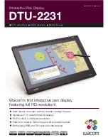
DTU-2231
Brand: Wacom Pages: 2

INTUOS 4
Brand: Wacom Pages: 2

GRAPHIRE 4
Brand: Wacom Pages: 2
CINTIQ 15X
Brand: Wacom Pages: 49

DTU-1031
Brand: Wacom Pages: 63
BAMBOO TOUCH
Brand: Wacom Pages: 2

Cintiq 22HD
Brand: Wacom Pages: 65
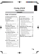
Cintiq 21UX
Brand: Wacom Pages: 34

12WX
Brand: Wacom Pages: 2
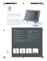
Cintiq 21UX
Brand: Wacom Pages: 2
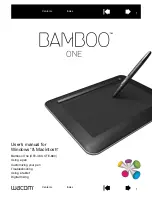
BAMBOO
Brand: Wacom Pages: 56
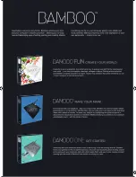
BAMBOO
Brand: Wacom Pages: 2
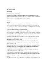
DTU-1031AX
Brand: Wacom Pages: 4

MD 85276
Brand: Medion Pages: 22

ZAGGfolio
Brand: Zagg Pages: 2

HX-TT100
Brand: Jam Pages: 2

MPDCG71
Brand: MPMan Pages: 25


