background image

25

Settings

Settings Menu

5.2.5  Brightness

The 

Brightness 

setting allows you to set the lighting level of the display (

Figure 5-10

). 

Use the 

Up / Down

 control buttons to change the brightness setting, each press of incrementally 

changes the lighting level by 10%. 

Press the 

N

 button to return to the settings menu.

Figure 5-10 

Brightness Settings Screen

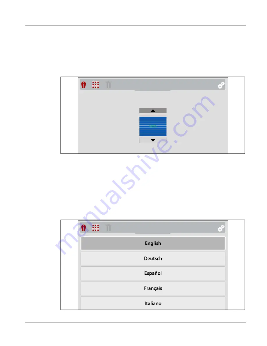
5.2.6  Language

Selecting 

Language 

from the menu allows you to select the your preferred language 

(

Figure 5-11

). 

Use the 

Up / Down

 control buttons to make a selection from the menu, then press the 

Y

 button to 

enable the selection and return to the settings menu. 

Menu Options: 

English

French

Spanish

Italian

Polish

Dutch

German

Portuguese 

(Brazil).


Figure 5-11 

Language Menu

Summary of Contents for ELITE

Page 1: ...Diagnostic Thermal Imager ELITE User Manual ...

Page 2: ...rty software licensed by Keil an ARM Company Copyright 2004 2014 Keil An ARM Company This device contains third party software licensed by FLIR Systems Commercial Vision Systems Copyright 2011 2012 2013 2014 FLIR Systems THIS SOFTWARE IS PROVIDED BY THE COPYRIGHT HOLDERS AND CONTRIBUTORS AS IS AND ANY EXPRESS OR IMPLIED WARRANTIES INCLUDING BUT NOT LIMITED TO THE IMPLIED WARRANTIES OF MERCHANTABIL...

Page 3: ...erms and conditions of the purchase lease or rental agreement under the terms of which the equipment to which this manual relates was acquired Increases in any way the liability to the customer or to third parties Snap on reserves the right to make changes at any time without notice IMPORTANT Before operating or maintaining this unit please read this manual carefully paying extra attention to the ...

Page 4: ...a circuit different from that to which the receiver is connected Consult the dealer or an experienced radio TV technician for help CAUTION You are cautioned that changes or modifications not expressly approved by the party responsible for compliance could void your authority to operate the equipment FCC RF Radiation Exposure Statement 1 This transmitter must not be co located or operating in conju...

Page 5: ...bsite http diagnostics snapon co uk Phone 44 0 845 601 4736 E mail diagnosticsUKproductsupport snapon com Australia and New Zealand Website http www snapontools com au Phone Australia 1800 810 581 New Zealand 0800 762 766 E mail sota diagnostics snapon com The Netherlands and Belgium Website http www eurotechcenter nl Phone NL 31 0 356 242322 BE 32 0 380 80537 E mail helpdesk eurotechcenter nl Deu...

Page 6: ...onnecting to Wi Fi ALTUSDRIVE com 9 Basic Operation Live Mode 9 Special Button Functions Live Mode 9 Changing View Settings Live Mode 10 About Temperature Readings 11 Using Full Thermal Mode 12 Using Overlay Opacity Mode 12 Using Visual Light Camera Mode 14 Using the Menu Menu Mode 15 Using the LED Spotlight 17 Chapter 5 Settings 18 Main Topic Links 18 Settings Menu 19 Wi Fi Connection 20 ALTUS Se...

Page 7: ...Features 41 Important Notes 41 Registration Getting Started 42 ALTUS New User Registration 42 ALTUS SureTrack User Setup 43 Using ALTUS 44 Navigating ALTUS Toolbars 45 Quick Reference ALTUS Operation 45 My Files 46 Search 51 Favorites 52 Profile 53 Chapter 9 Application Examples 58 Examples 59 Chapter 10 Maintenance 62 Main Topic Links 62 Storage 62 Cleaning 62 Battery Pack 63 Safety Guidelines 63...

Page 8: ...vii Contents Check Router Settings 73 Clearing Wi Fi Networks 73 General Wi Fi Troubleshooting 74 ...

Page 9: ...ions and variations in the products that can be tested with this instrument we cannot possibly anticipate or provide advice or safety messages to cover every situation It is the responsibility of the automotive technician to be knowledgeable of the system being tested It is essential to use proper service methods and test procedures It is important to perform tests in an appropriate and acceptable...

Page 10: ...rate or minor injury to the operator or to bystanders Safety Message Conventions Safety messages are provided to help prevent personal injury and equipment damage Safety messages communicate the hazard hazard avoidance and possible consequences using three different type styles Normal type states the hazard Bold type states how to avoid the hazard Italic type states the possible consequences of no...

Page 11: ...phasis is used in procedures to highlight selectable items such as buttons and menu options Example Select Functions 1 1 2 Symbols The greater than arrow indicates an abbreviated set of selection instructions Example Select Utilities Tool Setup Date The above statement abbreviates the following procedure 1 Select the Utilities icon 2 Select the Tool Setup submenu 3 Highlight the Date option from t...

Page 12: ...t indicates a situation which if not avoided may result in damage to the test equipment or vehicle Example IMPORTANT Do not use any abrasive cleansers or automotive chemicals on the tool 1 1 5 Hyperlinks Hyperlinks or links that take you to other related articles procedures and illustrations are available in electronic documents Blue colored text indicates a selectable hyperlink Example IMPORTANT ...

Page 13: ...age Memory Capacity 15000 images or 225 video recordings total depends on the number and size of the files Image File Format bmp Video File Format avi USB Interface 2 0 USB micro USB Battery Rechargeable Lithium Ion Battery Pack 3 7V 2800mAh nominal Approximate 4 hour continuous operation with the brightness level setting at 50 Approximate 80 charge in 3 hours 100 charge in less than 5 hours USB P...

Page 14: ...tions Wi Fi Features FCC IC ETSI CE TELEC Certified IEEE 802 11 Compliant b g n with single band 2 4 GHz WLAN Transmit Power 17 dBm WLAN Receive Sensitivity 97 dBm 1Mbps WPA WPA2 Personal WEP Item Description Specification ...

Page 15: ...t overlay and full thermal In addition the thermal imager includes a built in feature that automatically transfers captured images to your ALTUS account ALTUS ALTUSDRIVE com is a mobile friendly cloud based site designed specifically for technicians to store organize and share information see ALTUS ALTUSDRIVE com Image Sharing Storage on page 41 3 1 General Features Figure 3 1 1 Power On Off Butto...

Page 16: ... the Imager Always keep the protective cover closed during operation Only open the protective cover during battery charging or when connecting to the PC or removing the microSD card Opening the protective cover during operation could result in an electrostatic discharge event that may cause the Thermal Imager to reset If this occurs the Thermal Imager will reset and return to normal operation with...

Page 17: ...evel Icon 5 Center Region Temperature Average 6 Target Center Region Temperature Average 7 Menu Indicator Tab 8 Color Palette Maximum Temperature Value 9 Color Palette Range Indicator 10 Color Palette Minimum Temperature Value Figure 3 2 Default Screen Features 8 Up Down Control Buttons Directional Dual Function Live Mode press to change the overlay opacity setting See Special Button Functions Liv...

Page 18: ... an audible tone is sounded upon startup After the introductory screen fades the Thermal Imager switches into Live mode When in Live mode the device is in live capture mode and allows you to make thermal measurements and capture still images and video in various modes of visible light and thermal views See Basic Operation Live Mode on page 9 Onscreen Navigational Tips are provided for select menu ...

Page 19: ...displays objects similar to a standard visible light digital camera see Using Visual Light Camera Mode on page 14 Overlay displays objects using visible light with a transparent thermal image overlay see Overlay Mode Operation Options on page 13 Full Thermal displays objects as a full thermal image only see Using Full Thermal Mode on page 12 4 4 1 Special Button Functions Live Mode When in Live Mo...

Page 20: ...can be changed at any time while in Live mode using either visual light thermal or overlay settings Typical examples of the available view settings are shown below Use the Left Right control buttons to toggle through the display settings 1X Zoom Picture in Picture 2X Zoom Split Screen 3X Zoom ...

Page 21: ...ess and cause no interruption in operation Symbols are used to indicate when temperatures are out of the scale range and are described in the following chart Center Region Temperature Average and Palette Range Indicator The target indicator in the center of the screen measures the Center Region Temperature Average The Center Region Temperature Average is dynamically indicated within the color pale...

Page 22: ...see Changing View Settings Live Mode on page 10 To change the emissivity settings see Emissivity on page 29 for additional information See Settings on page 18 for information on all device settings The thermal image is displayed using the color palette selected to define object temperatures Use the color palette range indicator to determine the temperature of objects within the thermal image To ch...

Page 23: ...t on page 17 To change view settings e g zoom picture in picture split screen see Changing View Settings Live Mode on page 10 To change the emissivity settings see Emissivity on page 29 for additional information See Settings on page 18 for information on all device settings The thermal image is displayed using the color palette selected to define object temperatures Use the color palette range in...

Page 24: ...under the opacity icon The imager is now in Visual Light Mode 0 opacity 2 Point the imager at the desired object s Figure 4 2 Visual Light Mode Operation Options Pull the Screen Capture Trigger to save an image of the active screen See Capturing and Saving Images on page 32 for additional information Press the N button to start stop video recording See Recording and Saving Video on page 33 for add...

Page 25: ... of saved images see Using the Gallery Viewing Deleting on page 33 3 Delete Icon Use to delete saved images shown grayed out see Using the Gallery Viewing Deleting on page 33 4 Settings Icon Opens the device settings menu see Settings Menu on page 19 Figure 4 4 Button Menu Mode Button Operations Video Recording Enable Disable video recoding mode see Recording and Saving Video on page 33 LED Spotli...

Page 26: ... that appear grayed out transparent indicate that they are not applicable The last menu viewed is displayed when the Menu button is pressed 6 To select a menu option press the Up Down control buttons Figure 4 5 If more options are available than can be displayed onscreen use the Down button to scroll down through the options 7 When finished press the Menu button to exit Figure 4 5 ...

Page 27: ...ge level approximately one bar indication on icon the LED flashlight is disabled The spotlight will be functional again when the battery has been charged to approximately 30 Always turn the spotlight off before and when charging the battery NOTE i A fully charged battery pack can provide up to 4 hours of continuous operation The battery discharge rate will vary depending on overall use and setting...

Page 28: ...to a Wi Fi network Disconnecting from a network or remove password Wi Fi Status Icon Identification ALTUS Setup Date and Time Color Palette Brightness Language Automatic Shutdown Navigation Tips Spotlight Intensity Thermal Camera Calibration Advanced Temperature Emissivity Object Distance Wi Fi Status Micro SD card check About Factory Reset ...

Page 29: ...igure 5 1 2 Use the Left Right control buttons to select the Settings icon from the toolbar Figure 5 2 Figure 5 2 3 Use the Up Down control buttons to select an option from the menu NOTE i You can return to Live mode at anytime by pressing the Menu button 4 Press the Y button to open the selected setting option Figure 5 3 Settings Icon ...

Page 30: ...a wireless network Figure 5 4 1 Turn on the thermal imager and press the Menu button 2 From the toolbar select the Settings icon 3 Select Wi Fi Connection from the menu 4 To turn Wi Fi on off press the UP control button to select the Wi Fi Power icon then press the Y button to turn toggle Wi Fi on off Figure 5 4 Figure 5 4 Wi Fi On Off Network Selection 5 Press the Down control button to enter the...

Page 31: ...egistration Getting Started on page 42 Use the QR code to open ALTUSDRIVE com on your mobile device Figure 5 6 IMPORTANT If you are a new owner of this tool you must register this device with your ALTUS account in order to transfer files to your ALTUS account If you do not register the device with your ALTUS account captured files will be sent to the previous owners ALTUS account If you do not hav...

Page 32: ...n The following chart shows the WI Fi icons used to indicate connection status Wi Fi ON Connected to network access point and Internet Wi Fi ON Alternate available network access point Wi Fi ON Not connected to network access point or Internet Wi Fi ON Network access point password protected Wi Fi ON Connected to network not connected to Internet Wi Fi ON Actively connecting to network access poin...

Page 33: ...ting ALTUS Setup displays the following Device Serial Number Code PIN ALTUSDRIVE com QR code This information is used when registering on ALTUSDRIVE com See ALTUS ALTUSDRIVE com Image Sharing Storage on page 41 for registration information Figure 5 7 ...

Page 34: ...n to continue to the next 2 After all selections have been made press the N button to return to the settings menu 5 2 4 Color Palette Different color palette themes can be used to help define enhance object temperatures onscreen by varying color ranges contrast and brightness Four color palette presets are available from the menu Figure 5 9 Use the Up Down control buttons to make a selection from ...

Page 35: ...10 Press the N button to return to the settings menu Figure 5 10 Brightness Settings Screen 5 2 6 Language Selecting Language from the menu allows you to select the your preferred language Figure 5 11 Use the Up Down control buttons to make a selection from the menu then press the Y button to enable the selection and return to the settings menu Menu Options English French Spanish Italian Polish Du...

Page 36: ...gation Tips Onscreen navigational tips are provided for select menu navigation procedures to help you become familiar with the Thermal Imager menus Each Tip will appear only once after turning on the Thermal Imager Selecting Navigation Tips from the settings menu allows you to turn on enable or turn off disable the automated navigational tips Figure 5 13 Use the Up Down control buttons to make a s...

Page 37: ...tness of the LED spotlight Figure 5 14 Three settings are provided Low Eco 7 lumens Medium 12 lumens High 22 lumens default setting Use the Up Down control buttons to make a selection from the menu then press the Y button to enable the selection and return to the settings menu Figure 5 14 Spotlight Intensity Menu ...

Page 38: ...ion will occur when the thermal imager is turned on during warm up An automatic calibration will occur approximately every 5 minutes and once at every 3 C temperature change of the thermal sensor An audible click may also be heard during calibration and a temporary screen freeze occurs A symbol is used to indicate calibration is about to occur see following table 5 2 11 Advanced Temperature The Te...

Page 39: ...nd the scope of this manual Core material makeup Surface condition Temperature Angle of view Wavelength As a general rule objects and surfaces normally exhibit emissivity ranging from approximately 0 1 to 0 95 Materials with smooth non oxidized surfaces usually range from 0 05 to 0 50 however these values may change if the surface is rough or oxidized The Thermal Imager is equipped with five commo...

Page 40: ...n of an object that appears to differ when viewed from different positions is known as parallax When objects are viewed closer than 1 foot 30 48 cm they will always display slightly mis aligned however as the imager is moved farther away from the object the misalignment decreases Therefore to optimize the accuracy of the thermal imager when used in close proximity of an object 1 to 3 feet 30 48 to...

Page 41: ...n Tips Disabled Spotlight Intensity High Object Distance Near Opacity Overlay Level 60 Zoom Level 3X Wi Fi Enable Enabled Wi Fi Password Password is deleted When Factory Reset is selected a confirmation screen is displayed select the Y button to proceed with the reset or the N button to cancel If Y is selected a confirmation screen displays to indicate the reset was completed and then the option t...

Page 42: ...your ALTUS account at ALTUSDRIVE com see ALTUS ALTUSDRIVE com Image Sharing Storage on page 41 2 After the image is saved you can continue operation as normal save another image or view the image saved on the microSD card in the Gallery see Using the Gallery Viewing Deleting on page 33 Approximately 15000 images or 225 video files can be saved to the microSD card The overall total of images and vi...

Page 43: ...w the video saved on the microSD card in the Gallery see Using the Gallery Viewing Deleting on page 33 Approximately 15000 images or 225 video files can be saved to the microSD card The overall total of images and videos that can be saved to the microSD card will vary and depends on number and size of all files saved 6 4 Using the Gallery Viewing Deleting 6 4 1 Opening the Gallery and Selecting a ...

Page 44: ...ile Date Time 4 Delete Icon 5 Current Image of Total indicator e g 1 of 36 6 Selected File displays in background Figure 6 3 Image Gallery Screen A file upload status icon is used on the file name selection Figure 6 3 to indicate the current status of the file upload to ALTUS See ALTUS ALTUSDRIVE com Image Sharing Storage on page 41 for additional information File Upload Status Icons File Not Uplo...

Page 45: ...select and view other files in the Gallery list scroll through the list using the Up Down control buttons 2 Press the N button to return to the main menu 6 4 3 Deleting Images from the Gallery 1 Open the Gallery see Opening the Gallery and Selecting a File 2 Select the file to be deleted from the Gallery list 3 Select the Delete trash can icon from the toolbar Figure 6 5 Figure 6 5 Delete Icon 4 P...

Page 46: ...C turned on connect the USB cable to your PC 4 The Thermal Imager will be recognized by your PC as an external storage device e g USB Drive E USB Drive H etc Figure 6 6 Figure 6 6 Typical PC screens 5 Using the standard Windows applications on your PC e g Windows Explorer or Computer select your saved files from the USERDATA folder on the Thermal Imager microSD card Figure 6 6 Select a file image ...

Page 47: ...0 from the following systems Powertrain and Exhaust Body and Electrical Chassis and Brakes HVAC Other options available from menu List All Tips Lists all the tips from the systems shown above Demonstration Demonstration Mode on page 40 When the Thermal Imager is connected by USB cable to a PC the expert tips feature is disabled If the expert tips icon is selected while the USB cable is connected t...

Page 48: ...results Additional sub menu selections may be required depending on the selection Figure 7 3 Component Menu 5 Results are displayed Figure 7 4 Use the Up Down control buttons to scroll through the results The results are identified as Know Good indicates the thermal image or video clip shown represents a known good component for comparison Known Bad indicates the thermal image or video clip shown ...

Page 49: ...s and or reference images may not be available for all components Expert tip screen examples are shown in Figure 7 4 Figure 7 4 6 When finished press the N button to return to the expert tips menu or press the Menu button to return to Live mode ...

Page 50: ...ion Figure 7 5 See Expert Tips on page 37 for navigation to the expert tips menu Figure 7 5 A thermal image or video clip example will appear on the screen Figure 7 6 Figure 7 6 Demonstration Thermal Image Video Example 2 Select the Down button to scroll through various expert tips NOTE i Scrolling of examples will restart again after the last image tip is selected 3 When finished press the N butt...

Page 51: ...ures Automatically transfer captured thermal images to your ALTUS account on ALTUSDRIVE com Access your online thermal image gallery using your mobile device or PC Share send individual images or your entire gallery via e mail Download images to your PC transfer print share Tag images attach descriptive text to help you search your image gallery Add images to Favorites for easy recall Use the Sear...

Page 52: ...d Code that are displayed when the device connects to the Wi Fi network or leave the screen displayed Codes can also be found in the Settings menu see ALTUS Setup on page 23 3 Using a mobile device or PC visit https ALTUSDRIVE com and select Create Individual Account from the Login screen 4 Enter the required information and create a Username and Password then select Create 5 At the Success confir...

Page 53: ...SDRIVE com and select Login upper right screen 4 Log in using your SureTrack Username and Password 5 Open the Profile Manager additional login may be required 6 From the Device Management tab select Add Device 7 Enter your Serial Number PIN Code and Device Name 8 Log out of Profile Manager then select the ALTUS Home Page browser tab to get started 9 Turn the thermal imager off and then on 10 See U...

Page 54: ...stration Getting Started on page 42 The thermal imager must be connected to a Wi Fi network see Wi Fi Connection on page 20 z Logging in to ALTUS registered user 1 Using your mobile device or PC visit ALTUSDRIVE com 2 Select the Login icon Figure 8 1 Figure 8 1 3 Log in using your Username and Password Figure 8 2 Figure 8 2 ...

Page 55: ...ions See callout 4 in My Files on page 46 Printing Files Select the menu icon on the image card upper right then select Download from the menu options see callout 4 in My Files on page 46 once downloaded print the file from your device Alternate Method open the file in a new browser tab see File Detail Tags on page 47 and use the browser viewer tools to print the file Note All browsers may not sup...

Page 56: ...Name See File Detail Tags on page 47 for additional information 3 Your Account Username and timestamp See Account on page 54 for additional information The timestamp indicates the date time the file posted on ALTUSDRIVE com 4 Menu Icon options Download Select to download the image to your device Delete Select to delete the image from ALTUS 5 Favorites Icon See Favorites on page 52 for additional i...

Page 57: ... Image Sharing Storage Using ALTUS File Detail Tags As shown in Figure 8 6 selecting touching an image from My Files opens the image File Detail card Selecting the image again opens that image in a new browser tab Figure 8 6 ...

Page 58: ...hanumeric in the description field as desired 6 Known Good Bad Checkboxes user defined and searchable Selecting a checkbox automatically creates a tag e g good and is displayed in the Active Tag s field 7 Tag user entered searchable text Enter text alphanumeric in this field as desired Tagging an image allows you to associate tag descriptive text to an image Tagging can be used to associate multip...

Page 59: ...idual Image Link icon To share an image 1 Select the Link icon Figure 8 8 on the image card Figure 8 8 2 Select Copy to Clipboard Figure 8 9 from the pop up window Figure 8 9 3 Open your e mail text social media etc app and paste the URL into a message to share with others The URL link that is sent only displays The Image Image Name Your User Name Date Image was posted Image Description Media Type...

Page 60: ...gure 8 10 from the upper toolbar Figure 8 10 2 Select Share My Gallery 3 Select Copy to Clipboard Figure 8 11 from the pop up window Figure 8 11 4 Open your e mail text social media etc app and paste the URL into a message to share with others The URL link that is sent is only displays The Images Image Names Your User Name Date the Images were posted Image Descriptions ...

Page 61: ...search box and select the magnifying glass icon Figure 8 12 or press Enter Figure 8 12 Search queries the following to find results Image File Name name can be either system assigned or user assigned Known Good Bad Checkboxes selecting a checkbox automatically creates a searchable tag e g good or bad Description user entered text Tag user entered text See File Detail Tags on page 47 for additional...

Page 62: ...es screen displays all the images selected as favorites Figure 8 13 Figure 8 13 To set a file as a Favorite select the Favorite icon star symbol to highlight the icon The Favorites icon can be selected deselected at anytime when displaying files Description Icon Favorite on Favorite off ...

Page 63: ...le Manager opens a new browser tab To return to ALTUS after logging out of Profile Manager you must select the ALTUS Home Page browser tab Enter your Username and Password at the Login screen If you are a SureTrack user please note that Profile Manager is the same as your SureTrack Profile Manager Any changes you make will also be reflected in your SureTrack account Profile Manager includes five t...

Page 64: ...ring Storage Using ALTUS Account This screen manages the following account information Figure 8 15 Authorization Key not required for ALTUS account registration Account Expiration Date Shop Nickname Email Username Password Figure 8 15 ...

Page 65: ...ion Figure 8 16 First Name Last Name City State Zip Code Figure 8 16 Expertise SureTrack users only Select the vehicles from the list that you have expertise with When a question is asked within the SureTrack community about one of the selected vehicles you will receive an email with the details and a link back to the question Figure 8 17 ...

Page 66: ...Diagnostic Tool Enter the device Serial Number serial number of the device Code authorization code specific to the device PIN specific PIN associated to the device Device Name user define name When finished select Save to save and link the device to your account Figure 8 18 Logging Out of Profile Manager Select the logout icon upper right screen to log out of Profile Manager Figure 8 19 Figure 8 1...

Page 67: ...57 ALTUS ALTUSDRIVE com Image Sharing Storage Using ALTUS Logging Out of ALTUS To log out of ALTUS select Profile from lower toolbar then select Logout Figure 8 20 Figure 8 20 ...

Page 68: ...ler A C Compressor Alternator Water Pump etc Differential Bearings and Fluid Intercooler Radiator Thermostat Coolant Passages Hoses Control Valves Heated IAC Engine Block Heater O2 Sensor Heater Glow Plugs EGR Oil Transmission and Inverter Coolers Pumps Electrical General Temperature Checks Open Short High Resistance Conditions Battery Cables Wiring Relays and Switches Heated Seats Mirrors Wipers ...

Page 69: ...re Blower Motor Typical Motorcycle Component Checks Powertrain Exhaust General Temperature Checks Cylinder Exhaust temperature misfire Exhaust Leaks Radiator Thermostat Coolant Passages Hoses Drive System Electrical General Temperature Checks Open Short High Resistance Conditions Battery Cables Wiring Connectors Relays and Switches Heated Seat and Grips Chassis Brakes General Temperature Checks Be...

Page 70: ...60 Application Examples Examples Coolant Control Valve Heater Core Intercooler Catalytic Converter Alternator Bearing Cabin HVAC Leaks Description Thermal Image Example ...

Page 71: ...61 Application Examples Examples Heated Seats Differential Bearing Wheel Bearing Hub Assy Motorcycle Heated Grip Split Screen Electrical Relays Picture in Picture view Description Thermal Image Example ...

Page 72: ... the following tasks to keep your Thermal Imager in proper working order Check the housing display and controls for dirt and damage before and after each use Clean the Thermal Imager housing and display screen with a damp soft cloth and a weak detergent cleaner IMPORTANT Do not use paper towel or other paper type materials to clean the display screen Do not use any abrasive cleansers or automotive...

Page 73: ... has been modified or damaged Use the battery pack for the specified product only Store the battery pack in a cool dry well ventilated area Follow all safety guidelines when handling the battery pack Read understand and follow all safety messages and instructions in this manual and in the Important Safety Instructions supplied with the Thermal Imager 51 1 Risk of electric shock Prior to recycling ...

Page 74: ...cable connected to a powered PC USB jack Medium Rate approximate charge rate 500mA Thermal Imager turned off USB cable connected to a powered PC USB jack High Rate approximate charge rate 960mA Thermal Imager turned off Using supplied or compatible USB power supply adapter connected to AC power source A protective cover is used over the USB jack and microSD card slot located on top of the Imager A...

Page 75: ...o a live AC power source NOTE NOTE i The battery pack will also charge when the USB cable is connected to a PC using the power supplied from the PCs USB connection The battery charge indicator LED is located on the front of the Thermal Imager above the control buttons Figure 10 2 A red LED is turned on to indicate the battery is being charged A green LED indicates the battery is fully charged 1 Ba...

Page 76: ...s power is being supplied by the internal battery pack Horizontal bars diminish as the battery discharges When the battery charge level drops to approximately 10 minutes of power left the icon will flash on off as a reminder to connect the USB power supply adapter If the charger is not connected the unit will continue operate until it automatically turns off due to low power A warning message will...

Page 77: ...re 10 4 IMPORTANT Do not pull the battery harness out of the housing Figure 10 4 3 Insert the battery connector into the battery pack until it locks clicks into place NOTE NOTE i Do not force the battery pack into the Thermal Imager it should set easily into place 4 Feed the slacked harness into housing as you install the battery pack into the housing Figure 10 5 Figure 10 5 ...

Page 78: ...0 6 Figure 10 6 NOTE NOTE i Date and time settings will need to be reset whenever the battery is reconnected after being disconnected 10 4 5 Ordering a Replacement Battery Contact your sales representative to order a replacement battery IMPORTANT Replace the battery pack with a Snap on replacement battery pack only ...

Page 79: ...ct North America Rechargeable Battery Recycling Corporation RBRC at http www rbrc org or http www call2recycle org or call 1 800 822 8837 USA United Kingdom Electrical Waste Recycling Company at http www electricalwaste com Australia Australian Battery Recycling Initiative http www batteryrecycling org au New Zealand Ministry for the Environment https www mfe govt nz issues waste streams batteries...

Page 80: ...or place imager in a dry area at room temperature until condensation clears Temperature measurement display is non responsive a If the symbol displays in front of the Center Region Temperature Average value this indicates the maximum measurable temperature has been reached e g 840 F 450 C b The Thermal Imager may be performing an automatic calibration Wait a few seconds and retry if still no respo...

Page 81: ... Fi signals Network Connection Also called Wi Fi connection The configured Wi Fi router connection the diagnostic thermal imager connects to This connection can be secured password protected or unsecured open 11 2 1 Wi Fi Icon Identification The following chart shows the WI Fi icons used to indicate connection status Wi Fi ON Connected to network access point and Internet Wi Fi ON Alternate availa...

Page 82: ... status indicators that can be used to troubleshoot Wi Fi connection issues Symbols are used to indicate status Yes Connected check mark and No Not Connected X mark Figure 11 2 Wi Fi module Wi Fi radio on off Connected to router network access point Connected to the network access point or router yes no Internet access Connected to the Internet yes no Valid serial number Device serial number is va...

Page 83: ... any corrections as necessary then retest for connectivity Contact your IT administrator or ISP for assistance 1 Check your router connection and if applicable the remote wireless access point connection 2 Clear saved Wi Fi networks see Clearing Wi Fi Networks on page 73 3 Verify a Router is configured to use Dynamic Host Configuration Protocol DHCP not a static IP address b Router and or settings...

Page 84: ...ress the UP button to select the Wi Fi Power icon then press the Y button to turn Wi Fi on 4 Connect to a known good network Not connecting to a network 1 Clear saved Wi Fi networks see Clearing Wi Fi Networks on page 73 2 Connect to a known good network Wi Fi connection drops off or disconnects intermittently Wi Fi Signal strength insufficient Check Wi Fi signal strength out of range or interfere...

Reviews: