


Wireless Video Scope
10 Snap-on
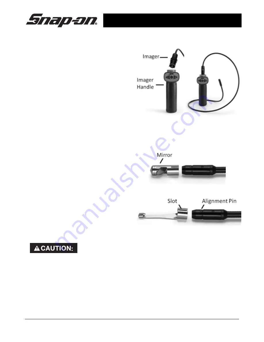
To connect the Imager to the
Imager Handle:
1.
Make sure the keyed ends are
properly aligned.
2.
Press imager connector firmly into the
unit until the retaining ring is
completely engaged.
If the keyed ends are not properly
aligned, the connector will not be fully
seated. Match up the arrows when
inserting the imager. In this case,
rotate the imager connector until the
tabs are fully seated. The imager
connector should only need to rotate a
maximum of 180 degrees.
Connecting the Imager to the Imager Handle
Installing an Accessory
The two included accessories, (mirror and
magnet) attach to the imager the same
way.
To connect the mirror:
Match up the Slot in the Mirror with
the Alignment Pin on the Imager and
push together to lock in place.
Installing Accessory-Mirror
Installing Accessory-Slot and Alignment Pin
Tool and Work Area Setup
To prevent serious injury, proper setup of the tool and work area is required. The
following procedures should be followed:
1.
Review the
General Safety Information
(on page 4) of this manual.
2.
Check work area for: adequate lighting, flammable liquids, vapors or dust that may
ignite.
3.
Follow tool set-up according to specific tool operator's manual.


