EVB-USB2660/USB2660i Evaluation Board Revision A User Manual
Revision 1.0 (06-09-09)
8
SMSC EVB-USB2660/60i Revision A
USER MANUAL
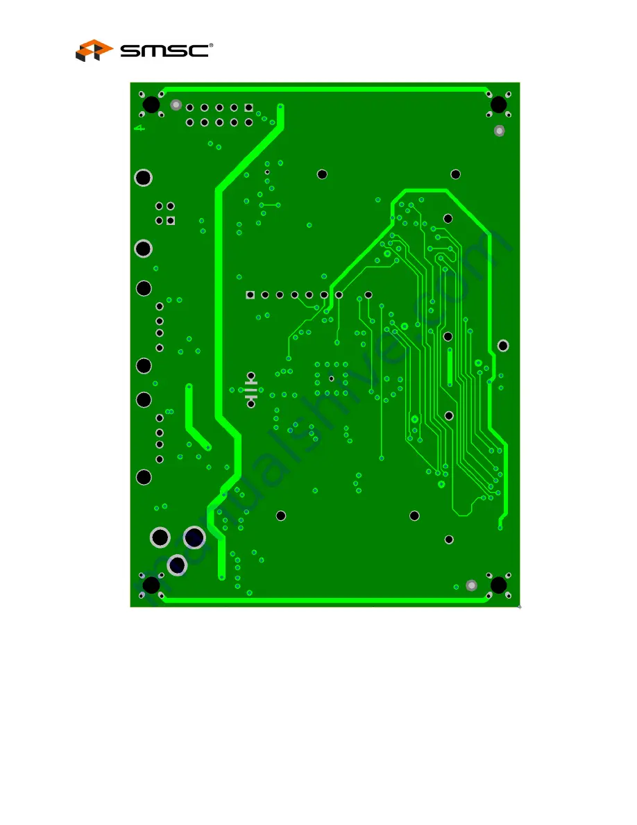
Figure 2.2 EVB_USB2660/60i Bottom Layer - Solder Side
Page 1: ...Sale Agreement may be obtained by visiting SMSC s website at http www smsc com SMSC is a registered trademark of Standard Microsystems Corporation SMSC Product names and company names are the trademar...
Page 2: ...n the evaluation board to provide firmware updates via USB by using the SMSC provided USBDM utility as required Default configuration can be changed by adding an EEPROM into the provided footprint How...
Page 3: ...figuration options optional External SPI flash for configuration options optional External SPI flash for USB downloadable firmware optional Low cost 4 Layer space saving design Self powered operation...
Page 4: ...ption The EVB USB2660 60i can load configuration from an external two wire I2 C EEPROM U4 The EEPROM must be installed at U4 and the SPI device at U3 should be removed to enable this option The EEPROM...
Page 5: ...ctors 2 1 7 Connector Description The EVB USB2660 60i has a set of standard USB style connectors one of type B for the upstream port and two of type A for downstream ports It also has a standard set o...
Page 6: ...ent side top layer is shown in Figure 2 1 with silk screen information to identify component locations Layer 1 1 9 2 8 mil finished Pre preg 4 25 mil 0 25 mil FR 4 Layer 2 1 3 mil nominal Core 45 mil...
Page 7: ...EVB USB2660 USB2660i Evaluation Board Revision A User Manual SMSC EVB USB2660 60i Revision A 7 Revision 1 0 06 09 09 USER MANUAL Figure 2 1 EVB_USB2660 60i Top Layer Component Side...
Page 8: ...EVB USB2660 USB2660i Evaluation Board Revision A User Manual Revision 1 0 06 09 09 8 SMSC EVB USB2660 60i Revision A USER MANUAL Figure 2 2 EVB_USB2660 60i Bottom Layer Solder Side...