


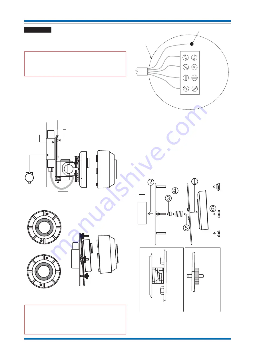
Installation
The
beam sensor pair
consist of two heads a
receiver head and a transmitter head, each head is
designed to fit into a
bracket having a base
.
"
The beam sensor TRANSMITTER head and
RECEIVER head should be installed on the same loop
facing each other for alignment purposes.
a.
Check the contents of the bracket and base package:
Component
Quantity
B base assembly
1
Screws
2
Terminal Block
1
Gasket
1
"
The junction box used for mounting the
bracket must be of the galvanised type. The 2-way base
can be recognised by the black plastic PCB cover
moulding.
b.
Fit the
terminal block
supplied into the junction box and
make the loop cable connection. Ensure the cable earth
connects to an earth point in the junction box.
c.
Secure the
angle bracket
assembly onto the junction box
using the gasket and
angle bracket
fixings.
d.
The applicable
sensor head
may now be fitted to the base
assembly by twist and lock action.
Parallel bracket assembly
Follow assembly in step order from
to
.
Installation instructions
32
Beam Transmitter head
Beam Tx
Beam Receiver head
Beam Rx
Bracket fixing screws
cover plate
Galvanised
Steel Junction
box
Angle
bracket
Gasket
Beam sensor
head
Parallel bracket
with base
Beam Sensor
Angle bracket
with base
JUNCTION BOX
EARTH TO
JUNCTION BOX
L1
0V
L2
0V
L1 (1)
0V (4)
0V(2)
L2 (3)
E ARTH (5)
Numbers in brackets refer
to alternative cable sleeve markings
which may be used to denote wires.
Ensure plate is flush
against the washer
Ensure nut is securely
fitted to the plate
Base
Adjustable Plate
Fixed Plate
Fixing nuts
Junction
box
Spring
washer
Fixing nuts
Adjustable
Plate
Adjustable
Plate
Fixed
Plate
Summary of Contents for SenTRI
Page 49: ...Notes 49 SenTRI ONE System...
Page 50: ...Notes Installation instructions 50...
Page 51: ...Notes 51 SenTRI ONE System...