background image

  Treadmill Assembly

Attention!
The following instructions are included only as information so that you, the con-
sumer, understand basically how the treadmill is assembled.

STEP 1:

  Remove treadmill from carton.  You may pick the rear of the treadmill up and

roll it off the packaging.  Remove foam padding, wrap, etc.  

Observe for possible

freight damage.

     Note:  

You will need a phillips screw driver and 1/2” wrench to complete assembly.

STEP 2: 

 This owners manual packet contains (2) Allen wrenches and (4) black plugs.

When practical, assembly hardware is mounted in appropriate locations that require
removal and replacement.  The computer head is loose.  Set aside for step 6.

STEP 3:  

An unpainted steel channel connects the console uprights to the base.  With

phillips screwdriver and Allen wrench (provided) unbolt the console uprights from base.
Discard plastic washers (4) and steel channels.  The 5/16” x 1” Allen bolts and “gold”
special nut/washers will be used in step 5.  The black phillips head screws will be used
in step 8.

STEP 4: 

  Raise the console upright assembly and place upright console assembly into

front grill area.  Be careful of the two cables.  A bottom and rear 3/8” pin will help locate
into proper position to allow hardware installation.  Locate the (4) 5/16” x 1” black Allen
bolts and “gold” special 5/16” washer/nuts removed in step 4.  Place one bolt on the end of
the Allen wrench (provided) and insert thru any one of (4) round frame holes.  Bolt
should go thru console hole to allow “gold” 5/16” hex nut/washer to be started.  Hand
“run” the nut against the console so that it will not turn during tightening with Allen
wrench.  Do not tighten with Allen wrench until all (4) nut/bolt assemblies are inserted
and started.  Tighten all bolts.  Nuts should “hold” without a wrench.  If they do not hold
use an open end wrench from the bottom.  Insert the (4) black plugs into the access
holes.

Note:

  For heavy use units it is advisable to use a wrench on the nuts and add addi-

tional torque to nut / bolt.

STEP 5:  

Handles will install thru access holes in console upright.  Remove both

5/16” Allen bolts in each handle with included wrench that is located in parts bag.  Slide
handle (flair to outside) thru access holes in console upright.  

Use caution to avoid

data cables in left hand side console upright.

  You may observe data cable clear-

ance from top of open console upright.  Start both bolts into hand rail thru console
upright.  Repeat procedure for opposite hand rail.  

Tighten all bolts.

3

Smooth 9.1 / 9.6

2/06/01

Summary of Contents for SMOOTH 9.6H

Page 1: ...lbynet com advancedfitness com The Fitness Superstore SALES 888 9TREADS 888 987 3237 SERVICE 888 800 1167 ext 103 SMOOTH is a registered trademark of Internetfitness com Mt Laurel NJ OWNER S MANUAL SMOOTH 9 6H ...

Page 2: ...ildren away from the treadmill There are obvious pinch points and other caution areas that can cause harm Keep hands away from all moving parts Never operate the treadmill if it has a damaged cord or plug If it is not working properly call your dealer Keep the cord away from heated surfaces Do not operate where aerosol spray products are being used or where oxygen is being administered Never opera...

Page 3: ...ate outlet that is properly installed and grounded in accordance with all local codes and ordinances DANGER Improper connection of the equipment grounding conductor can result in a risk of electric shock Check with a qualified electrician or serviceman if you are in doubt as to whether the product is properly grounded Do not modify the plug provided with the product if it will not fit the outlet h...

Page 4: ... bottom and rear 3 8 pin will help locate into proper position to allow hardware installation Locate the 4 5 16 x 1 black Allen bolts and gold special 5 16 washer nuts removed in step 4 Place one bolt on the end of the Allen wrench provided and insert thru any one of 4 round frame holes Bolt should go thru console hole to allow gold 5 16 hex nut washer to be started Hand run the nut against the co...

Page 5: ... Install motor hood and secure with 2 black phillips head screws removed in step 4 Front of motor hood is not secured The dealer must provide the following minimum n Follow the belt tracking instructions closely in order to ensure proper belt tension and path n Walk on the belt at slow speeds under 2 5 mph for a few minutes in order to break in the belt deck lubricant n Make certain treadmill is e...

Page 6: ... set to function properly with little finger pressure Pushing harder is not going to make the unit go faster or slower If you feel the buttons are not functioning properly with normal pressure contact your Smooth dealer adjustments can be made All buttons should operate and control treadmill functions without excessive finger effort Damage to overlay will result if excessive control pressure conti...

Page 7: ... to begin belt movement Clock will begin Speed Incline Repeat Feature The computer will retain the speed incline value you ve just selected as a repeater feature This means the next time the unit wakes lights up your desired start speed incline will repeat itself Anytime before belt movement is begun the speed or incline start value can be changed and held in memory Pause Feature Step 1 When opera...

Page 8: ...ess and release red STOP PAUSE switch while in pause mode Display will blank out Use this method when possible 2 Pull tether cord Should be used only in panic situation Hour Meter Feature When the tether cord is initially placed in operational position the Distance window will display total hours The Speed window indicates upper computer software version This is a service issue to refer to compute...

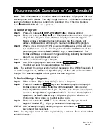
Page 9: ...e pre determined by our team of exercise experts If you make any changes before you begin exercising or during exercise the changes will be erased once the machine has been turned off at the end of your program and will return to the original factory program Definition of the Factory Defined Programs P1 Interval Trainer This program is designed to increase your endurance and build your lung power ...

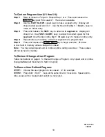
Page 10: ...fter selecting a program press and release START BELT key Treadmill will begin to move and workout has begun Note The segment time will always be 1 20th of the session time Within 5 seconds of the end of a segment run Incline and Speed displays will flash with a chime to alert a change This statement applies to both pre set and user programs To Review Change a Program Step 1 Refer to above Repeat ...

Page 11: ... incline entry Step 4 Repeat above procedures until all 10 segments are programmed Step 5 Press and release the START BELT key to begin exercise Exercise is now held in memory unless changed or erased Note You may adjust speed and or incline anytime during a workout These values will not be held in memory To Review Change a User Program Follow instructions on page 9 To Review Change a Program Any ...

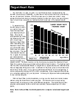
Page 12: ...lar reasons for or goals of exercise are cardiovascular fitness training for the heart and lungs and weight control The black columns on the chart above represent the Maximum Heart Rate for a person whose age is listed at the bottom of each column The training heart rate for either cardiovascular fitness or weight loss is represented by two different lines that cut diagonally through the chart A d...

Page 13: ...ap doesn t effect performance 6 Your workout must be within range distance between transmitter receiver to achieve a strong steady signal as noted by flashing light The length of range may vary somewhat but generally stay close enough to the console to maintain good strong reliable flashes pulses Usually an improper distance will indicate error until you move closer Wearing the transmitter immedia...

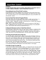
Page 14: ...ed by your physician Obviously a low maximum incline may result in more speed adjustments See Heart Rate Control Operation Selecting a Heart Rate Control Program You have the option during the setup mode to choose either the Weight Control pro gram or the Cardiovascular program Weight Control attempts to maintain your heart rate at 65 of your Maximum Heart Rate Cardiovascular attempts to maintain ...

Page 15: ...ase your speed using a flashing light bar on the display If the machine declines to 0 and your heart rate continues to exceed the Target Heart Rate the treadmill will prompt you to de crease your speed using a flashing light bar on the display If the treadmill is unable to receive a signal from the transmitter or if it detects an error the Actual Heart Rate window will display and the treadmill s ...

Page 16: ...t rate is displayed in the Incline window It will change as target is adjusted Note The above is a calculation only You may adjust your target to your personal level You may skip Step 4 by pressing the ENTER key before above adjustments are made STEP 5 Press the ENTER key and adjust speed with the Fasts Slowt key to desired level STEP 6 Press and release the START BELT key to begin belt movement N...

Page 17: ...that may accumulate UNPLUG POWER CORD BEFORE THIS TASK BELTADJUSTMENTS Treadbelt Tension Adjustment Belt tension is not critical for most users It is very important for joggers and runners in order to provide a smooth steady running surface Adjustment must be made from the right side of the rear roller in order to adjust tension with the 1 4 allen wrench provided in the parts package The adjustmen...

Page 18: ...n and wait a few minutes for the belt to adjust itself Continue to make 1 4 turns until the belt stabilizes in the center of the running deck The belt may require periodic tracking adjustment depending on use and walking running characteristics Some users will affect tracking differently Expect to make adjustments as required to center the treadbelt Adjustments will become less of a maintenance co...

Page 19: ...mill defect Contact your Smooth dealer See General Maintenance section under Belt Tracking A user may be walking while favoring or putting more weight on either the left or right foot If this walking pattern is natural track the belt slightly off center to the side opposite from the belt movement See Maintenance section on Treadbelt Tension Adjust as necessary Make certain clock is running This in...

Page 20: ...hasbeendamagedorrendereddefective a asaresultofaccident misuse orabuse b bytheuseof parts not manufactured or sold by Smooth c by modification of the Product or normal wear and tear d operation on incorrect power supplies or e asaresultofservicebyanyoneotherthanSmooth oranauthorizedSmoothwarrantyserviceprovider Productonwhichthe serial number has been defaced or removed is not eligible for warrant...

Page 21: ...tes to products distributed by Internet Fitness com under the Smooth brand name The warranty period to the original purchaser for the DRIVE MOTOR is ten 10 years from date of purchase effective on or after March 1 2001 FOR THE CONSUMER Please retain this page as proof of your new Drive Motor Warranty for future reference This Limited Warranty applies in the United States to products manufactured o...

Reviews: