Smithy CX-239 Quick Start Manual Download Page 6

Quick-Start Guide for Smithy Metal-Working Machine

Opening the Crate

Dec 2008

6

O

Oppeenniinngg tthhee C

Crraattee

Follow these steps to open the crate.

CAUTION!

Step 1

Step 2

Step 3

Step 4

CAUTION!

Step 5

Step 6

Step 7

Wear leather work gloves and safety glasses for this operation, especially

when cutting the metal bands, which are under tension.

Remove the packing list from the plastic bag attached to the crate and put the docu-

ment in a safe place.

Cut the metal bands encircling the crate with tin snips. 

Note: If you have ordered a

Granite or Granite Industrial machine, the plywood crate cover has been

screwed to the pallet. Unscrew the top two screws on the two plates on both

sides of the crate and the one plate on the end of the crate.

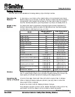
Determine the end of the crate at which the tailstock is located. You may need to lift

the crate 3 or 4 inches, and run your hand along the base. If you feel 10 to 12 inch-

es of sheet metal, you need to the lift the opposite end.

Using the proper lifting techniques, lift the tailstock end of the top of the crate

upward. To avoid pinching your fingers while lifting, place your hands toward the

corners of the crate and not in the middle. While lifting, pull the crate toward you

slightly so that it easily clears the tailstock.

Crate covers can weight up to 100 pounds. Ask a friend or family member to

help, if necessary.

Set the crate aside, out of the immediate work area. You may want to keep the

crate in case you ever need to return the machine for repair.

Check the packing list against the contents of the crate to ensure that everything

listed is accounted for in your shipment. Also, check the contents of the crate

against the inventory lists in the operating guide to ensure that all machine compo-

nents are present.

Check the machine carefully for signs of damage, especially if you noted damage to

the crate earlier.

!!

!!

Summary of Contents for CX-239

Page 1: ...can cause injury to you or others Please read this guide and the operating guide carefully before you start machining Proper use will create a safe working environment and prolong the life of your machine In this manual the symbols below draw attention to specific operating issues For pre delivery questions not covered in the guide dial 1 800 476 4849 Monday through Friday 8 00 a m to 5 00 p m Eas...

Page 2: ... on Track and Confirm UPS If we are given your email address at the time of ordering we will enter it when we fill out your shipping paperwork UPS will send you automatic updates as your shipment moves We make every effort to ship your complete order by one method Big heavy items like Smithys Smithy workstations and machine stands are delivered by truck If your order contains more than one major i...

Page 3: ...t in the drawing below Note the suggested clearances for the other sides of the machine Machines with 110 volt motors require a properly grounded 3 wire 110 volt AC electrical circuit protected by a 20 ampere 20 amp breaker Machines equipped with 220 volt motors require a 220 volt AC circuit single phase protected by a 15 ampere 15 amp 220 volt breaker Preferably the outlet should be on a separate...

Page 4: ...for loading at the shipping terminal On arrival thoroughly check each crate and carton for signs of loss or damage While a shipping company employee is present open any crate or carton that shows signs of loss or damage Examine the contents with the shipping company employee If any damage is present record an exact detailed description of the results of the examination on both the shipper s and yo...

Page 5: ...le The loading procedure depends upon your vehicle and the facilities at the terminal If the shipping company s forklift is not restricted to the loading dock you can have the crate loaded directly into the truck or trailer bed with the forklift as shown below at left If the forklift is restricted to the loading dock chains or straps can be used to lift the crate and lower it into the truck or tra...

Page 6: ...to lift the crate 3 or 4 inches and run your hand along the base If you feel 10 to 12 inch es of sheet metal you need to the lift the opposite end Using the proper lifting techniques lift the tailstock end of the top of the crate upward To avoid pinching your fingers while lifting place your hands toward the corners of the crate and not in the middle While lifting pull the crate toward you slightl...

Page 7: ...Remove the Smithy boxes that contain your Quick Start Pack Use wrenches to remove the nuts and bolts that hold the machine base to the pal let Pull out the four lifting handles in the base of the machine There are two lifting han dles on the operator s side of the machine and two on the back side of the machine On each side there is a lifting handle near the millhead and one near the tailstock Rem...

Page 8: ... the bench Remove any hold down straps and the plastic protective covering Use wrenches to remove the nuts and bolts that hold the machine base to the pal let Remove the Smithy boxes that contain your Quick Start Pak Remove the Millhead see diagram below Lock the millhead locking handle Using a sharp knife or razor blade score the paint where the millhead attaches to the headstock Depending on the...

Page 9: ...the tailstock The gib for the 1200 series is on the operator s side of the machine Remove the Lathe Chuck see diagram below Removal of the lathe chuck depends on which Smithy machine you have GN 1300 Series Using the chuck key supplied with the machine turn the square sockets in the spindle flange counterclockwise until the hashmarks are aligned Remove the chuck without letting it fall onto the ma...

Page 10: ...ated on either the operator s side as shown below or at the end of the bed Tap lightly on the right trestle to loosen it from the lathe bed Do not remove the locating pins You will need them in place to realign the carriage Engage the half nut run the carriage to the right and off the rack and slide the carriage off the bed As you are removing the carriage the gib and locking pin could fall out Be...

Page 11: ...1340 1340 MX 1340 IMX and for all Dedicated Lathes and Mills include all necessary mounting hardware The chip tray of the 80 045 bench comes with three mounting pads for the machine two mounting pads are pre drilled The two pads that are closest together support the headstock end of the machine and should be on the left side when fac ing your work bench from the operating side The easiest way to a...

Page 12: ...continued Bolt Patterns 1200 Series Mounting Bolt Layout 1300 Series Mounting Bolt Layout If you have made your own work bench use the lay out diagrams below to pre drill holes for the mounting hardware Continued on the next page Midas 1220 LTD 3 holes 0 5 inch diameter Midas 1220 XL 3 holes 0 5 inch diameter GN 1324 GN 1324 MX IMX 4 holes 0 5 inch diameter GN 1340 GN 1340MX IMX 4 holes 0 5 inch d...

Page 13: ...ng and Setup Note Hole size is 1 2 Use 3 8 to mount to your stand When you have completed securing the machine to the bench top you are ready to begin cleaning and setting up the machine Watch the DVD and read your operation guide thoroughly to familiarize yourself with your machine and the operations of your machine Pulleybox 69 25 10 8 25 12 25 8 25 0 75 11 5 3 75 4 5 0 75 7 0 75 0 75 6 875 0 62...

Reviews: