background image

4

Introduction

PARTS MANUALS AVAILABLE ONLINE AT smithco.com

SAFETY

Read and understand this manual and all safety signs before operating and maintaining.  Review the safety
instructions and precautions annually.

TAKE NOTE!  THIS SAFETY ALERT SYMBOL FOUND THROUGHOUT THIS MANUAL IS USED TO CALL
YOUR ATTENTION TO INSTRUCTIONS INVOLVING YOUR PERSONAL SAFETY AND THE SAFETY OF
OTHERS.  FAILURE TO FOLLOW THESE INSTRUCTIONS CAN RESULT IN INJURY OR DEATH.

THIS SYMBOL MEANS

- ATTENTION!

- BECOME ALERT!

- YOUR SAFETY IS INVOLVED!

SAFETY SIGNAL WORDS

Note the use of the signal words DANGER, WARNING and CAUTION with the safety messages.  The
appropriate signal word for each has been selected using the following guidelines:

DANGER:  Red. Indicates an imminently hazardous situation that, if not avoided, will result in death or
serious injury.  This signal word is to be limited to the most extreme situations typically for machine
components which, for functional purposes, cannot be guarded.

WARNING:  Orange. Indicates a potentially hazardous situation that, if not avoided, could result in
death or serious injury, and includes hazards that are exposed when guards are removed.  It may also
be used to alert against unsafe practices.

CAUTION:  Yellow. Indicates a potentially hazardous situation that, if not avoided, may result in minor
or moderate injury.  It may also be used to alert against unsafe practices.

Summary of Contents for Spray Star 1011

Page 1: ...Spray Star 1011 SharpShooter w Raven 440 with 15 Booms November 2015 Operator s Product Support Hwy SS Poplar Ave Cameron WI 54822 1 800 891 9435 productsupport smithco com ...

Page 2: ...l Spray Equipment 8 Set Up 9 Controls Instruments 10 11 Operation 12 29 Operating Instructions 12 14 SharpShooter Raven 440 Console Features 15 16 Console Programming 17 Console Calibration 17 18 Initial Programming 19 23 Spray Operation 24 25 Re Calibration of Flow Meter 25 Turf Management 26 Hose Handgun Spraying 26 Troubleshooting Nozzle Valves 27 29 Reference 30 31 Collecton TImes 30 Declarati...

Page 3: ... they have safety operat ing assembly and maintenance instructions Failure to do so could result in personal injury or equipment dam age Keep manuals in a safe place after operator and maintenance personnel have read them Right and left sides are from the operator s seat facing forward All Smithco Smithco Smithco Smithco Smithco machines have a Serial Number and Model Number Both numbers are neede...

Page 4: ...elease Hydraulic Oil Level Choke Open Choke Closed Hand Throttle Hour Meter Hour Meter Fuse Glow Plug Glow Plug Off Glow Plug On RPM Gasoline Diesel Water Temperature Temperature Light Engine Oil Engine Stop Engine Start Engine Run No Electrical Power Electrical Power Read Operator s Manual ...

Page 5: ...MBOLS No Smoking Moving Parts Manual Operation Pinch Point Step Hot Surface Hydraulic Fluid Penetration Lift Arm Tractor Engage Disengage PTO Ground Speed Fast Slow H High L Low F Forward R Reverse N Neutral Warning Danger Caution Up Raise Down Lower Up DownArrow ...

Page 6: ...TION with the safety messages The appropriate signal word for each has been selected using the following guidelines DANGER Red Indicates an imminently hazardous situation that if not avoided will result in death or serious injury This signal word is to be limited to the most extreme situations typically for machine components which for functional purposes cannot be guarded WARNING Orange Indicates...

Page 7: ... and Left Tank Sides B 25 356 Decal Tire Pressure 20psi All Wheels C 25 352 Decal Bypass Valve Hang Tag on pump D 25 298 Decal Warning Hot Tailpipe Guard D 25 286 Decal Crush Pinch Hood Back Edge Both Sides RH Control Panel E 15 719 Decal Speed Control LH Control Panel 27 093 Decal Oil Level LH Control Panel F 25 370 Decal 88 dba LH Front Panel 15 463 Decal Spray Pump LH Front Panel G 15 672 Decal...

Page 8: ...11 Disengage all drives and set park brake before starting the engine 12 Never use your hands to search for oil leaks Hydraulic fluid under pressure can penetrate the skin and cause serious injury 13 This machine demands your attention To prevent loss of control or tipping of the vehicle A Use extra caution in backing up the vehicle Ensure area is clear B Do not stop or start suddenly on any slope...

Page 9: ... 10 Check hoses for weak or worn condition before each use Make certain that all connections are tight and secure 11 Do not operate unit with leaks frayed kinked hoses or tubing Repair or replace immediately 12 Use only pipe hose and fittings rated for maximum pressure or pressure at which pressure relief valve is set at When replacing pipe hose or fittings use new product 13 Do not operate an eng...

Page 10: ...eed 0 8 mph 0 12 8 kph Reverse Speed 0 3 mph 0 4 8 kph BATTERY Automotive type 24F 12 Volt BCI Group Size 24 Cold Cranking Amps 575 minimum Ground Terminal Polarity Negative Maximum Length 10 25 26 cm Maximum Width 6 88 17 cm Maximum Height 10 25 cm FLUIDCAPACITY Crankcase Oil See Engine Manual Fuel 6 gallon 22 7 liters Hydraulic Fluid 5 gallon 19 liters Grade of Hydraulic Fluid SAE 10W 40 API Ser...

Page 11: ...hen cold DO NOT OVERFILL 4 Fill fuel tank located on the right side with Unleaded 87 Octane gasoline minimum Fuel is flammable caution must be used when storing or handling it Do not fill fuel tank while engine is running or an enclosed area fumes are explosive and dangerous to inhale DO NOT SMOKE while filling the fuel tank DO NOT OVERFILL 5 Machine should be greased before starting refer to Spra...

Page 12: ...he buzzer sounds if the pump is running dry F Lights This rocker switch turns lights on by pushing on the top and off by pushing on the bottom G Spray Pump This rocker switch turns the spray pump on by pushing on the top and off by pushing on the bottom H Left Boom Switch This rocker switch lifts and lowers the left boom I Right Boom Switch This rocker switch lifts and lowers the right boom J Chok...

Page 13: ... accelerator pedal range N Master Boom Switch is used to override the master switch on the computer console of the spray systems O Reverse Pedal This pedal controls ground speed in the reverse direction P Accelerator Pedal This pedal controls ground speed Press pedal to increase speed Varying the amount of movement of the pedal will vary the ground speed MASTERBOOMSWITCH The master boom switch P l...

Page 14: ...ews etc and tighten or replace as needed 5 Inspect hydraulic lines for damage or leaks Never use hands to inspect for leaks 6 Check the hydraulic fluid level The hydraulic fluid tank is located under the seat The fluid level should be 2 2 5 6 4 cm from the top of the tank when cold Use only SAE 10W 40 API Service SJ or higher Motor Oil 7 Inspect the steering throttle and shift linkages for good ho...

Page 15: ... Charge battery at 15 amps for 10 minutes or 7 amps for 30 minutes Do not exceed the recommended charging rate If electrolyte starts boiling over decrease charging Always remove grounded battery clamp first and replace it last Avoid hazards by 1 Filling batteries in well ventilated areas 2 Wear eye protection and rubber gloves 3 Avoid breathing fumes when electrolyte is added 4 Avoid spilling or d...

Page 16: ...7 6 28 8 5 32 4 2 15 9 50 3 4 12 2 46 2 5 32 5 5 20 8 100 6 9 17 5 66 2 3 16 3 6 13 6 25 1 7 9 1 34 4 3 16 5 6 21 2 50 33 4 14 3 54 1 3 16 7 9 29 9 100 6 9 18 7 70 8 You can change orifice disc sizes to enhance spray system performance Smaller discs reduce amount of agita tion desirable in some foaming materials and make more dischargeable liquid available for nozzles Larger or none discs increase...

Page 17: ...15 Operation PARTS MANUALSAVAILABLE ONLINE AT smithco com Decrease Flow Increase Pressure Rocker Switch PSI PWM RAVEN440WITHSHARPSHOOTER FEATURES ...

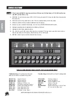
Page 18: ...alculator This key is also used to select an area base measurement of US acres SI Hectares or TU 1 000 sq ft H ENTER Used only to enter the data into the Console SEE QUICK REFERENCE PAGE FOR DATATHAT SHOULD BE ENTERED Calibration Keys Top Row Used to enter Function Keys Bottom Row Used to display data data into console to calibrate the system BOOM 1 CAL Length of Boom 1 TOTALAREA Total Area Spraye...

Page 19: ...boom in inches centimeters by multiplying the number of tips times the spacing Write these boom widths down for future reference when programming the Console computer The Console is capable of controlling up to three 3 booms CALCULATING SPEEDCAL 1 Enter Speed Cal in key of 785 for GPS 2 Place Master and Boom 1 switches to on 3 Enter 0 in key 4 Drive 1 mile Do not use vehicle odometer to determine ...

Page 20: ...efine this number See definitions below Valve Backlash Controls the time of the first correction pulse after a change in correction direction is detected Incr to Decr or Decr to Incr Range 1 to 9 1 Short Pulse 9 Long Pulse Valve Speed Digit Controls the Speed of the Control Valve motor Running the Control Valve too fast will cause the system to oscillate Range 1 to 9 1 slow 9 Fast Brake Point Digi...

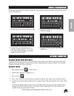
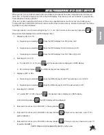
Page 21: ...y Steps the DATA display from US acres to SI b Depressing momentarily Steps the DATA display from SI Hectares to TU c Depressing momentarily Steps the DATA display from TU 1000 sq ft to US 2 Selecting US SI or TU a To select US SI or TU step until the desired code is displayed in DATA display b Momentarily depress the DATA display will now display SP1 3 Displaying SP1 or SP2 a Depressing momentari...

Page 22: ...e system 13 Enter the estimated total Volume in Tank when you start spraying in key labeled Each time the tank is refilled this number must be reentered 14 Enter the TIME of day in the key labeled This is a 24 hour clock Therefore all time after 12 59 pm add 12 hours Thus 8 30 am is entered as 8 30 but 1 30 pm is entered as 13 30 in the keyboard OTHERDISPLAYFEATURES 1 To display TOTALAREA covered ...

Page 23: ...ill be alternately displayed SELFTESTFEATURE SELF TEST allows speed simulation for testing the system while the vehicle is not moving Enter the simulated operating speed in the key labeled If 6 MPH 10 km h is desired enter 6 0 10 0 Verify speed by de pressing key labeled SPEED The SELF TEST speed will clear itself when motion of vehicle is detected by the Speed Sensor A SPEED CAL Value of 900 230 ...

Page 24: ...e will appear b Enter new delay time 0 to 200 days using the same procedure as that for entering other data In the event of console power loss the power down delay time will default to 10 days CONSOLEALARMFEATURE Console alarm sounds if application rate is 30 or more away from target application rate for 5 seconds ALARMMENU Depress for 5 seconds until DATA display shows A on Depressing momentarily...

Page 25: ...30 seconds INITIALCONSOLESETUP 1 Fill tank with water only If positive displacement type pump is used fully open pressure relief valve PRV Open gate valve between the tank and pump 2 Place MASTER On Off to On and Boom On Off switches to Off 3 Place MAN RATE 1 RATE 2 switch to MAN 4 Place POWER On Off switch to On 5 Verify correct boom widths speed calibration meter calibration valve calibration 21...

Page 26: ...again and rinse tank interior thoroughly Remove cap from 3 way valve to drain 4 Rinse exterior of sprayer thoroughly with clean water 5 This sprayer is equipped with a self cleaning strainer The strainer uses the excess pump flow to bypass clogging particles back to the spray tank There is a gap between the tapered inner cylinder and the screen face that causes the inlet fluid to flow at a high ve...

Page 27: ... way and reset if an obstacle such as a tree or fence is in you path To minimize the chance for missed areas or double application use a device to mark the outside boundaries of each spray swath Foam markers and dye markers are advisable PROCEDURE TO RE CALIBRATE FLOWMETER 1 Enter a Meter Cal number of 10 in Meter Cal Button 2 Enter a Total Volume of Calibrating the Pressure Gauge in Total Volume ...

Page 28: ... there are many types and sizes of nozzles two specific types have proven most successful in turf grass management The first type is target directed It sprays material in a direct line downwards to the target turf grass These are flat fan nozzles commonly referred to as TeeJet nozzles They are available in a wide variety of sizes for any required discharge volume rate They are the best for many co...

Page 29: ...se nozzles to drip Operating a plugged nozzle valve for extended periods may result in nozzle valve coil failure Clean plugged nozzle valves immediately If plugged nozzles are a frequent problem in a particular boom section inspect the machines boom filter screens for plugged or damaged screens An 80 mesh screen is recommended to prevent nozzles from plugging Check the mesh size of the strainers a...

Page 30: ...om nozzle components by washing components with clean water After extended use the soft plunger seal Item 1 will wear a groove where the seal impacts the hard orifice seat Replace plunger if worn or damaged As the groove deepens the pressure capacity of the valve will decrease until the pressure capacity interferes with the operating pressure of the sprayer The result is erratic pulsing often desc...

Page 31: ...394 38 63636364 39 3 7 325 6 204 0 626535627 37 59213759 38 3 8 334 4 204 0 610047847 36 60287081 37 3 9 343 2 204 0 594405594 35 66433566 36 4 352 204 0 579545455 34 77272727 35 4 1 360 8 204 0 5654102 33 92461197 34 4 2 369 6 204 0 551948052 33 11688312 33 4 3 378 4 204 0 539112051 32 34672304 32 4 4 387 2 204 0 526859504 31 61157025 32 4 5 396 204 0 515151515 30 90909091 31 4 6 404 8 204 0 5039...

Page 32: ...MUKAISUUSVAKUUTUS ඵ DECLARATION DE CONFORMITE ඵ KONFORMITÄTSERKLÄRUNG ඵ ȴȸȿёɇȸ ɇɉɀɀɃɆɌёɇȸɇ ඵ MEGFELELSSÉGI NYILATKOZAT ඵ DICHIARAZIONE DI CONFORMITÀ ඵ ATBILST5BAS DEKLAR CIJA ඵ ATITIKTIES DEKLARACIJA ඵ DIKJARAZZJONI TALͲKONFORMITÀ ඵ DEKLARACJA ZGODNO_CI ඵ DECLARAÇÃO DE CONFORMIDADE ඵ DECLARAԐIE DE CONFORMITATE ඵ VYHLÁSENIE O ZHODE ඵ IZJAVA O SKLADNOSTI ඵ DECLARACIÓN DE CONFORMIDAD ඵ DEKLARATION OM...

Page 33: ...ntatsiooni ja kellel on õigus koostada tehniline toimik Sen henkilön allekirjoitus jolla on valmistajan valtuutus vakuutuksen laadintaan jolla on hallussaan teknisetasiakirjat joka on valtuutettu laatimaan tekniset asiakirjat ja joka on sijoittautunut yhteisöön Signature de la personne habilitée à rédiger la déclaration au nom du fabricant à détenir la documentationtechnique à compiler les fichier...

Page 34: ...f you need help locating an Authorized Smithco Distributor or if you have questions regarding your warranty rights or responsibilities you may contact us at Smithco Product Support Department 200 W Poplar PO Box 487 Cameron Wisconsin 54822 Telephone 1 800 891 9435 E Mail ProductSupport smithco com Maintenance Parts Parts scheduled for replacement as required maintenance Maintenance Parts are warra...

Page 35: ...nty gives you specific legal rights and you may also have other rights which vary from state to state THERE ARE NO OTHER EXPRESS WARRANTIES OTHER THAN THOSE SET FORTH ABOVE ALL IMPLIED WARRANTIES OF MERCHANTABILITY AND FITNESS FOR USE ARE LIMITED TO THE DURATION OF THE LIMITED WARRANTIES CONTAINED HEREIN Some states may not allow limitations on how long an implied warranty lasts so the above limit...

Reviews: