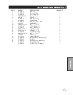


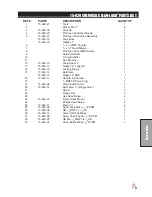

85
Accessories
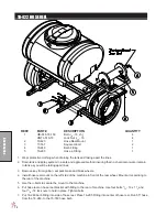
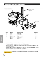
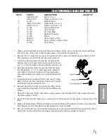
10-417 CHEMICAL CLEAN-LOAD
®
OPERATING INSTRUCTIONS
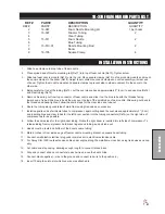
STARTUP
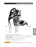
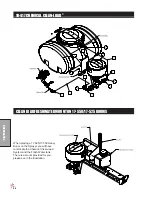
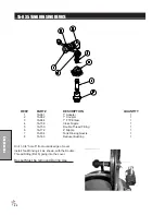
1. All Clean-load valves must be closed prior to starting: inlet ball valve, knife valve and hopper rinse ball valve.
2. Open lid to check for foreign objects which may hinder performance or contaminate the system.
3. Close and lock lid by turning cover clockwise.
4. Divert pump flow to Clean-load inlet line. A pressure of 30 PSI minimum and 150 PSI maximum must be used.
Highest pressures increase eduction rate and available wand suction.
5. Turn inlet ball valve on (yellow handle).
6. Open knife valve, located on the bottom of hopper, by pushing handle in (red handle).
7. Unlock and open lid slowly by turning cover counterclockwise.
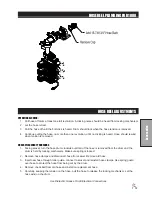
LOADING LIQUID OR POWDERED CHEMICAL INTO HOPPER
8. Pour required amount of chemical into hopper. Avoid splashing liquids or powdered chemicals outside of hopper.
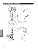
9. Rinse empty chemical containers if applicable. Place container opening over container rinse valve and press down.
This will activate the rinse valve and rinse container.
10. Rinse Clean-load hopper. Close and lock lid by turning cover clockwise. Release the safety locking band on the
hopper rinse ball valve and turn on for 20 seconds. Close ball valve and return locking band to locked position.
11. Open lid and inspect for chemical residue. Repeat step 10 as necessary.
12. Close knife valve by pulling red handle out towards you. Turn inlet (yellow handle) off.
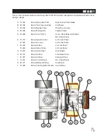
LOADING LIQUID AND/OR POWDERED CHEMICAL WITH SUCTION LANCE
Note: Lance suction is dependent upon eductor pressure and flow. For best results, use highest pressure avail
-
able up to 150 PSI maximum.
8. Insert lance body with o-ring into eductor until the o-ring is sealed.
9. Use the free end of the lance to pierce bag or container to vacuum powdered or liquid chemical.
10. Rinse lance. Place lance end into a clean container of water to rinse lance assembly.
11. Remove lance body from eductor and drain any remaining fluid into hopper.
12. Close knife valve (red handle). Turn inlet valve (yellow handle) off.
SHUTDOWN
1. Ensure that:
• All valves are closed. Be sure to close knife valve first. (Close by pulling red handle out towards you.)
• Chemical residue has been cleaned.
• Hopper lid is closed and locked by turning cover clockwise.
2. Divert pump flow back to normal operation.
Summary of Contents for 10-100-D
Page 13: ...11 NOTES ...
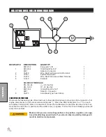
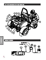
Page 14: ...12 Diagrams WIRING DIAGRAM ...
Page 16: ...14 Diagrams HYDRAULIC DIAGRAM ...
Page 18: ...16 Parts BODY FRAME DRAWING ...
Page 20: ...18 Parts NOSE CONE DRAWING ...
Page 22: ...20 Parts FRONT AXLE DRAWING ...
Page 24: ...22 Parts SEAT CONSOLE AND ROPS DRAWING ...
Page 26: ...24 Parts FUEL TANK DRAWING ...
Page 28: ...26 Parts OIL TANK OIL FILTER OIL COOLER DRAWING ...
Page 30: ...28 Parts FOOT PEDAL LINKAGE DRAWING ...
Page 32: ...30 Parts PUMP DRAWING ...
Page 34: ...32 Parts ENGINE DRAWING ...
Page 36: ...34 Parts PARK BRAKE DRAWING ...
Page 38: ...36 Parts REAR AXLE DRAWING ...
Page 40: ...38 Parts TANK DRAWING TURBO QUAD AGITATOR DRAWING ...
Page 42: ...40 Parts 10 576 ORBITROL DRAWING ...
Page 56: ...54 Accessories 17 835 BOOM DRAWING ...
Page 70: ...68 Accessories 16 906 ELECTRIC HOSE REEL DRAWING ...
Page 72: ...70 Accessories 16 129 MANUAL HOSE REEL DRAWING ...
Page 78: ...76 Accessories 10 378 FOAM MARKER FOR 1000 DRAWING WIRING DRAWING ...
Page 80: ...78 Accessories 10 378 FOAM MARKER DRAWING ...
Page 82: ...80 Accessories FOAMER NOZZLE MOUNT HOSE GUARD MOUNT DRAWING ...
Page 84: ...82 Accessories 14 291 FOAMER REPLACEMENT PARTS ...
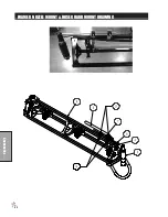
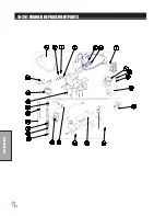
Page 90: ...88 Accessories 15 620 CHEMICAL CLEAN LOAD DRAWING ...