


79
Accessories
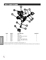
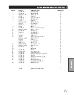
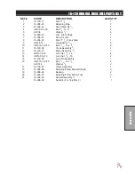
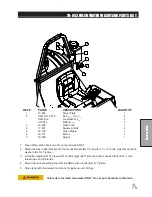
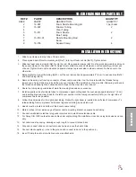
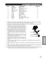
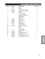
10-378 FOAM MARKER PARTS LIST
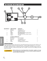
REF# PART#
DESCRIPTION
QUANTITY
1
HNTL-38-16
Lock Nut,
3
/
8
- 16
2
HW-38
Flat Washer,
3
/
8
4
HB-38-16-300
Bolt,
3
/
8
- 16 x 3
2
2
20-723
RH Bracket
1
3
HB-14-20-075
Hex Bolt,
1
/
4
-20 x
3
/
4
4
HNFL-14-20
Flange Lock Nut,
1
/
4
-20 4
4
20-726
LH Bracket
1
5
10-645
Foamer Plate
1
6
HB-516-18-075
Bolt,
5
/
16
- 18 x
3
/
4
4
HW-516
Flat Washer,
5
/
16
4
HNFL-516-18
Flange Whiz Nut,
5
/
16
- 18
4
7*
14-291-04
Tank Bracket
2
8*
14-291-02
Foamer Tank
1
9*
14-291-03
Compressor Only
1
14-291-01
Black Cover
1
10*
14-284-02
Cap Assembly
1
11*
Clear Tube
1
12*
Blue Tube
1
13*
14-291-05
Double Switch Box
1
33-508
Auto Blade Type Fuse 15amp
1
15-506-02
Switch - middle
1
14-291-14
Switch - outside
1
14
8803-6
Black Trim
1
*
14-291
Foamer
(includes parts 7-13)
1
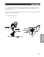
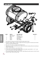
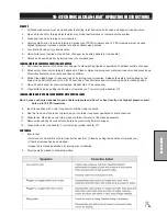
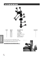
INSTALLATION
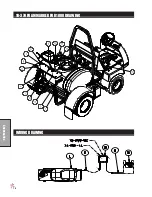
HOSES
Being careful not to cut the tubing, cut the over-sleeve back approximately 2" (5 cm) to expose blue and clear
tubing. Remove blue wing nut from top connector of foam nozzle and slide it on the blue tube with the threads
facing toward end of tube. Slide blue tube all the way over the top of the small tube on foam nozzle. Slide
wing nut back to the threads and hand tighten. Follow the same steps for the clear tube and tube nut.
Route the tubing along underside of main frame using tie downs as necessary.
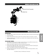
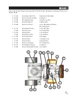
Install opposite ends of air-liquid tubes to compressor, again cutting back the over sleeve approximately 2" (5
cm) and inserting blue and clear tubes for the left boom section into the tubing connectors on the right side of
compressor as far as possible. Follow the same steps for the right boom tubing. Notice the right boom is in
-
serted into left side of compressor. To release tubing from compressor, hold black ring around tubing, and pull
tube out.
Summary of Contents for 10-100-D
Page 13: ...11 NOTES ...
Page 14: ...12 Diagrams WIRING DIAGRAM ...
Page 16: ...14 Diagrams HYDRAULIC DIAGRAM ...
Page 18: ...16 Parts BODY FRAME DRAWING ...
Page 20: ...18 Parts NOSE CONE DRAWING ...
Page 22: ...20 Parts FRONT AXLE DRAWING ...
Page 24: ...22 Parts SEAT CONSOLE AND ROPS DRAWING ...
Page 26: ...24 Parts FUEL TANK DRAWING ...
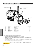
Page 28: ...26 Parts OIL TANK OIL FILTER OIL COOLER DRAWING ...
Page 30: ...28 Parts FOOT PEDAL LINKAGE DRAWING ...
Page 32: ...30 Parts PUMP DRAWING ...
Page 34: ...32 Parts ENGINE DRAWING ...
Page 36: ...34 Parts PARK BRAKE DRAWING ...
Page 38: ...36 Parts REAR AXLE DRAWING ...
Page 40: ...38 Parts TANK DRAWING TURBO QUAD AGITATOR DRAWING ...
Page 42: ...40 Parts 10 576 ORBITROL DRAWING ...
Page 56: ...54 Accessories 17 835 BOOM DRAWING ...
Page 70: ...68 Accessories 16 906 ELECTRIC HOSE REEL DRAWING ...
Page 72: ...70 Accessories 16 129 MANUAL HOSE REEL DRAWING ...
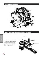
Page 78: ...76 Accessories 10 378 FOAM MARKER FOR 1000 DRAWING WIRING DRAWING ...
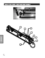
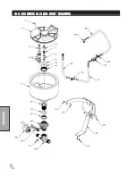
Page 80: ...78 Accessories 10 378 FOAM MARKER DRAWING ...
Page 82: ...80 Accessories FOAMER NOZZLE MOUNT HOSE GUARD MOUNT DRAWING ...
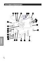
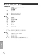
Page 84: ...82 Accessories 14 291 FOAMER REPLACEMENT PARTS ...
Page 90: ...88 Accessories 15 620 CHEMICAL CLEAN LOAD DRAWING ...