
67
Accessories
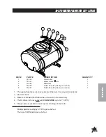
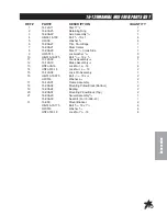
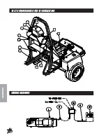
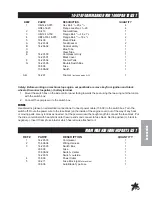
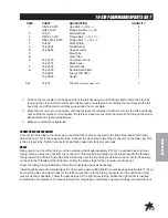
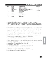
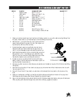
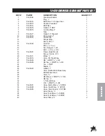
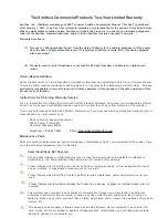
10-378 FOAM MARKER PARTS LIST
REF#
PART#
DESCRIPTION
QUANTITY
1
HB-14-20-075
Hex Bolt,
1
/
4
-20 x
3
/
4
4
HNFL-14-20
Flange Lock Nut,
1
/
4
-20
4
2
10-413
Foamer Brace
1
3
HB-12-13-150
Flange Bolt,
1
/
2
-13 x 1
1
/
2
1
4
HBFL-516-18-075
Flange Bolt,
5
/
16
-18 x
3
/
4
2
5
10-409
Mount Plate
1
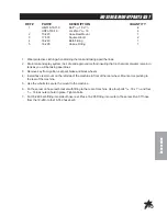
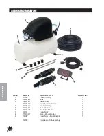
A
14-291-04
Tank Bracket
2
B
14-284-02
Cap Assembly
1
C
Blue Tube
1
D
Clear Tube
1
E
14-291-03
Compressor Only
1
14-291-01
Black Cover
1
F
14-291-02
Foamer Tank
1
G
14-291-05
Double Switch Box
1
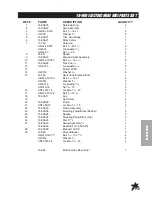
15-506-01
Fuse (F10A 250)
1
15-506-02
Switch
1
A-G
14-291
Foamer
(includes parts A-G)
1
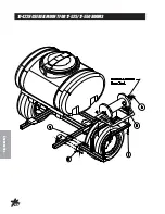
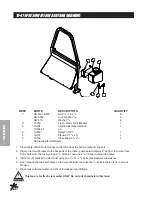
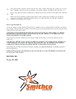
1. Position the mount plate on the back side of the roll bar using two 5/16 flange bolts. Install the brace by
removing the 1/2 bolt form the lefts side roll bar brace. reinstall the bolt, holding the two bracesto the roll
bar. Other end of foamer mount brace goes under the mount plate.
2. Place foamer unit onto mount plate, with cap facing to the left side of machine. Using 1/4 bolts and flange
nuts bolt foame marker to mount plate. the left rear moner mount of the foamer will oblt through the mount
plate and brace. Tighten all hardware.
3. Make sure all bolts are tightened.
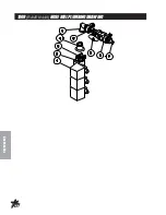
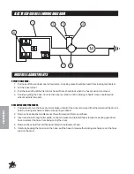
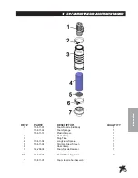
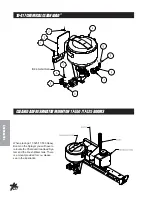
CONNECTING THE CAP ASSEMBLY
Connect the blue tube to the tank cap connector which is also connected to the large blue tube which hangs
below the cap. This is the soap outlet tube. Connect the clear tube to the other connector on the tank cap. This
is the air input tube. Tighten connectors hand tight, assembly tank cap onto tank.
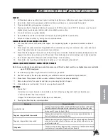
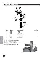
HOSES
Being careful not to cut the tubing, cut the oversleeve back approximately 2" (5 cm) to expose blue and clear
tubing. Remove blue wing nut from top connector of foam nozzle and slide it on the blue tube with the threads
facing toward end of tube. Slide blue tube all the way over the top of the small tube on foam nozzle. Slide wing
nut back to the threads and hand tighten. Follow the same steps for the clear tube and tube nut.
Route the tubing along underside of main frame using tie downs as necessary.
Install opposite ends of air-liquid tubes to compressor, again cutting back the oversleeve approximately 2" (5 cm)
and inserting blue and clear tubes for the left boom section into the tubing connectors on the right side of com-
pressor as far as possible. Follow the same steps for the right boom tubing. Notice the right boom is inserted
into left side of compressor. To release tubing from compressor, hold black ring around tubing, and pull tube out.
Summary of Contents for 10-100-C
Page 10: ...8 Service END USER S SERVICE CHART Duplicate this page for routine use...
Page 13: ...NOTES...
Page 14: ...12 Diagrams WIRING DIAGRAM...
Page 16: ...14 Diagrams HYDRAULIC DIAGRAM...
Page 18: ...16 Parts BODY FRAME DRAWING...
Page 20: ...18 Parts NOSECONEDRAWING...
Page 22: ...20 Parts FRONTAXLEDRAWING...
Page 24: ...22 Parts SEATCONSOLEANDROPSDRAWING...
Page 26: ...24 Parts FUELTANKDRAWING...
Page 28: ...26 Parts OILTANK OILFILTER OILCOOLERDRAWING...
Page 30: ...28 Parts FOOTPEDALLINKAGE DRAWING...
Page 32: ...30 Parts ENGINE PUMPSANDEXHAUSTDRAWING...
Page 34: ...32 Parts PARKBRAKEANDREARAXLEDRAWING...
Page 36: ...34 Parts TANKDRAWING TURBO QUADAGITATORDRAWING...
Page 38: ...36 Parts 15 301ORBITROLDRAWING...
Page 40: ...38 Parts 10 117 HYDRAULIC PUMP DRAWING...
Page 42: ...40 Parts 16 998HYPROPUMPDRAWING...
Page 44: ...42 Parts 10 116WHEELMOTOR 14 0 CI DRAWING...
Page 50: ...48 Accessories 16 524 MOTORIZEDCONTROLVALVEDRAWING 15 737STRAINER...
Page 52: ...50 Accessories 17 575 SMITHCOSUPERBOOM...
Page 56: ...54 Accessories 16 906ELECTRICHOSEREELDRAWING...
Page 58: ...56 Accessories 16 129MANUALHOSEREELDRAWING...
Page 60: ...58 Accessories 10 422HOSEREELMOUNT FOR17 525 17 550BOOMS...
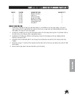
Page 62: ...60 Accessories 1008 RAVEN 440 HOSE REEL PLUMBING DRAWING...
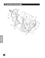
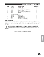
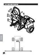
Page 66: ...64 Accessories 10 378FOAMMARKERFOR1000DRAWING WIRINGDRAWING...
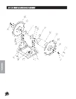
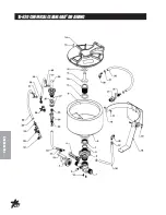
Page 68: ...66 Accessories 10 378FOAMMARKER DRAWING...
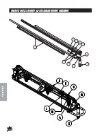
Page 70: ...68 Accessories FOAMER NOZZLEMOUNT HOSEGUARDMOUNTDRAWING...
Page 78: ...76 Accessories 15 620CHEMICALCLEANLOAD DRAWING...


