background image

Installation

13

EN

Instructions for wall mounting (primary 
system)

1. Assemble the fastening bracket.

2. Align the base of the hook on the 

fastening bracket with the base of the 
slot on the wall fastening plate.

3. Align the base of the fastening bracket 

with the ground and tighten the screws 
to fix the measurements.

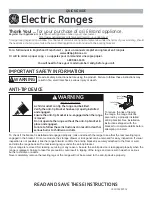
Summary of Contents for CPF36UGGAN

Page 1: ...oline or other flammable vapors or liquids in the vicinity of this or any other appliance WHAT TO DO IF YOU SMELL GAS Do not try to light any appliance Do not touch any electrical switch Do not use an...

Page 2: ...s burns to children or adults READ AND SAVE THESE INSTRUCTIONS Your safety and the safety of others are very important We have provided many important safety messages throughout this manual and on the...

Page 3: ...ange for the first time Keep these operating instructions in a safe place and pass them on to any future user NOTE This range is manufactured for use with natural gas To convert the appliance to LP Pr...

Page 4: ...70 ELECTRICAL CODE latest edition Or the CANADIAN ELECTRICAL CODE C22 11 1 and C22 2 No 01982 or latest edition and all local codes and ordinances IMPORTANT Observe all codes and ordinances in force...

Page 5: ...ppliance All adjustments and servicing must be performed by qualified installers or service technicians Do not leave the packing material around the home Sort the various items of waste and take them...

Page 6: ...teel 0 015 0 4 mm stainless steel 0 024 0 6 mm aluminum or 0 020 0 5 mm copper 35 889 mm min clearance between the top of the cooking surface and the bottom of an unprotected wood or metal cabinet 5 m...

Page 7: ...that do not satisfy the minimum cabinet clearances install a rangehood over the cooking surface to avoid burn hazards A 53 mm 2 2 16 B 660 mm 26 C 131 mm 5 2 16 D 34 mm 1 5 16 E 912 mm 35 15 16 F 809...

Page 8: ...al from the shipping base Remove angle mounting brackets from the range Due to the weight a dolly fork lift with soft rubber tread wheels should be used to move this unit The weight must be supported...

Page 9: ...t level on the floor to ensure stability Screw or unscrew the bottom part of the foot until the appliance is stable and level on the floor The adjustment range of the screw is 1 37 inches 35 mm NOTE I...

Page 10: ...qualified installer or contractor to determine the proper method for drilling holes through the wall or floor material such as ceramic tile hardwood etc Failure to follow these instructions may resul...

Page 11: ...ry system 1 Assemble the fastening bracket 2 Align the base of the hook on the fastening bracket with the base of the slot on the wall fastening plate 3 Align the base of the fastening bracket with th...

Page 12: ...nd at the same time insert the bracket in the plate fastened to the rear of the appliance Instructions for floor mounting secondary system The secondary anti tip device is to be attached to the floor...

Page 13: ...t should insert into one of the central slots at the rear 3 After having positioned and leveled the appliance move the bracket close to the rear of the appliance and anchor it to the floor 4 Lower the...

Page 14: ...d on the oven door frame These ID plates must never be removed Warning Electrical shock hazard Plug into a grounded 3 prong outlet Do not cut or remove the grounding prong Do not use an adaptor Do not...

Page 15: ...volt 60 Hz AC only 15 ampere fused electrical supply is required A time delay fuse or circuit breaker is recommended It is recommended that a separate circuit serving only this appliance be provided R...

Page 16: ...s in force The room where the appliance is installed must have enough air flow for the regular combustion of gas and the necessary air change in the room itself The air vents protected by grilles must...

Page 17: ...nnections indicate a leak If a leak appears shut off the gas valve controls and adjust the connections Then check the connections again Remove all the detergent product from the range Replace the part...

Page 18: ...lve must be disconnected from the gas supply piping system during any pressure testing of that system at test pressures greater than PSIG 3 5 kPa Testing below PSIG 3 5 kPa with a water column pressur...

Page 19: ...gn the holes 2 Secure the backguard to the top by tightening screws Installing the front skirting The front skirting must always be positioned and secured correctly on the appliance 1 Use a screwdrive...

Page 20: ...eviously removed screws Installing the side skirting After installing the front skirting the side skirting can be fastened correctly to the appliance 1 Use a screwdriver to remove the front screws und...

Page 21: ...readed elbow on the manifold You risk damage to this part of the appliance which may void the manufacturer s warranty Before leaving check all connections for gas leaks with soap and water DO NOT use...

Page 22: ...PAGE INTENTIONALLY LEFT BLANK...

Reviews: