background image


Instructions for the installer 


14


3.2


Burner and nozzle characteristics table 


Burner 


ULPG


(

PROPANE

)


2.75


KPa 


Nominal gas consumption 

(MJ/h) 

Injector 


(mm) 

Auxiliary 

3.9 

0.54 

Semi rapid 

6.3 

0.68 

Rapid 

10.8 

0.88 

WOK 

12.8 

1.00 


Burner 


NG


1.0


KPa 


Nominal gas consumption 

(MJ/h) 

Injector 


(mm) 

Auxiliary 

3.7 

0.90 

Semi rapid 

6.5 

1.20 

Rapid 

10.9 

1.55 

WOK 

12.7 

1.75 


3.3


Arrangement of burners on cooking hob 


BURNERS 
 
1


Auxiliary 

2


Semi rapid 

3


Rapid 

4


WOK 

5


WOK 


4.


FINAL OPERATIONS 

After replacing the nozzles, reposition the flame-spreader crowns, the 
burner caps and the grids. 


After adjustment to a different kind of gas from the one for which the 
cooker has been tested, replace the plate inside the storage 

compartment with one corresponding to the new kind of gas. This plate 

can be obtained from your nearest Authorised Assistance Centre. 


Summary of Contents for A21X-5

Page 1: ...__ 26 10 CLEANING AND MAINTENANCE ___________________________ 31 11 EXTRAORDINARY MAINTENANCE _________________________ 35 12 PROBLEMS AND CAUSES ________________________________ 37 Thank you for choosing our product We advise you to read this manual carefully It contains all necessary instructions for maintaining unaltered the appearance and functional qualities of the cooker INSTRUCTIONS FOR THE...
Page 2: ...TERIALS AND TAKE THEM TO THE NEAREST SPECIAL GARBAGE COLLECTION CENTRE IT IS OBLIGATORY FOR THE ELECTRICAL SYSTEM TO BE GROUNDED ACCORDING TO THE METHODS REQUIRED BY SAFETY RULES THE PLUG TO BE CONNECTED TO THE POWER CABLE AND THE SOCKET MUST BE THE SAME TYPE AND MUST CONFORM TO CURRENT REGULATIONS THE SOCKET MUST BE ACCESSIBLE AFTER THE APPLIANCE HAS BEEN BUILT IN NEVER UNPLUG BY PULLING ON THE C...

Page 3: ...AR OR PLAY WITH IT REPLACED APPLIANCES MUST BE TAKEN TO A SPECIAL GARBAGE COLLECTION CENTRE WHERE THIS APPLIANCE IS INSTALLED IN MARINE CRAFT OR IN CARAVANS IT SHALL NOT BE USED AS A SPACE HEATER DO NOT SPRAY AEROSOLS IN THE VICINITY OF THIS APPLIANCE WHILE IT IS IN OPERATION BEFORE THE APPLIANCE IS PUT INTO OPERATION ALL THE LABELS AND PROTECTIVE FILMS APPLIED INSIDE OR OUTSIDE MUST BE REMOVED Th...

Page 4: ...Introduction spares 6 ...

Page 5: ...cket must be the same type conforming to regulations in force Check that the power line is adequately grounded Do not use reducers adapters or shunts On the power line install an omnipolar cut off device with contact cut off distance greater than or equal to 3 mm located in an easily accessible position near the unit Use an H05RR F type three core cable 3 x 2 5 mm 2 The cable end to be connected t...

Page 6: ...Instructions for the installer 8 Overall dimensions location of gas and electrical connection points all measures in mm A 110 B 760 C 150 D 170 ...

Page 7: ...ision to allow the gas to be turned off and disconnected for servicing and removal of the appliance as required from the gas supply Before the appliance is operated make certain all relevant parts are placed in the correct position When the installation is completed the installation connections of appliance will require to be leak tested the burner operating pressure and flame checked and adjusted...

Page 8: ...alls This these opening s must have a free passage cross section of at least 100 cm2 or 200 cm2 for appliances not equipped with gas safety device These openings must be constructed so that they cannot be obstructed indoors or outdoors and should preferably be close to the floor on the side opposite to the combustion gas discharge point If it is not possible to make the openings in the room where ...

Page 9: ...t less than 150 mm above the hob for the full dimension width or depth of the cooking surface area Where the cooking appliance is fitted with a splashback protection of the rear wall is not required 3 Additional requirements for Freestanding and Elevated Cooking Appliaces Measurements D E Where D the distance from the periphery of the nearest burner to a horizontal combustible surface is less than...

Page 10: ...x the screw to the wall and hook the chain B 2 Hook the chain to the hole positioned at the rear of the cooker by the gas pipe A 3 Once the chain is in position push the cooker against the wall 4 The height of the screw hole from floor level must not exceed 800 mm C A B C ...

Page 11: ...es must be changed and the minimum flame adjusted on the gas taps To change the nozzles proceed as described below 3 1 Replacement of nozzles on the hob This operation requires no primary air regulation 1 Extract the grids and remove all the caps and flame spreader crowns 2 unscrew the burner nozzles with a 7 mm socket wrench 3 replace the nozzles according to the type of gas to be used and the de...

Page 12: ... 5 1 20 Rapid 10 9 1 55 WOK 12 7 1 75 3 3 Arrangement of burners on cooking hob BURNERS 1 Auxiliary 2 Semi rapid 3 Rapid 4 WOK 5 WOK 4 FINAL OPERATIONS After replacing the nozzles reposition the flame spreader crowns the burner caps and the grids After adjustment to a different kind of gas from the one for which the cooker has been tested replace the plate inside the storage compartment with one c...

Page 13: ...e the knob and check burner flame stability rapidly turning the knob from maximum to minimum position the flame should not go out Repeat the operation on all the gas taps 4 2 Positioning and levelling of the appliance Having carried out the electricity and gas hook up level the appliance using the four adjustable legs 4 3 Mounting the rear top upstand Position the upstand above the top taking care...

Page 14: ...ESCRIPTION OF SYMBOLS BACK LEFT BURNER BACK RIGHT BURNER FRONT LEFT BURNER FRONT RIGHT BURNER FRONT CENTRAL BURNER BACK CENTRAL BURNER MAIN OVEN THERMOSTAT AUXILIARY OVEN THERMOSTAT MAIN OVEN FUNCTIONS AUXILIARY OVEN FUNCTIONS COOKING HOB BURNER COMMAND KNOB The flame is lit by pressing the knob and turning it anticlockwise to maximum flame To adjust the flame turn the knob between maximum and min...

Page 15: ... at the programmed level Main oven Auxiliary oven FUNCTION SWITCH KNOB OVENS Turn the knob to select from the following functions Main oven Auxiliary oven MAIN OVEN AUXILIARY OVEN NO FUNCTION SET NO FUNCTION SET UPPER AND LOWER UPPER AND LOWER HEATING ELEMENT HEATING ELEMENT UPPER AND LOWER HEATING ELEMENT VENTILATION UPPER HEATING ELEMENT GRILL ELEMENT LOWER HEATING ELEMENT GRILL ELEMENT VENTILAT...

Page 16: ...s the key for 1 2 seconds to stop the display flashing and start setting of the current time Press the value modification keys or to increase or decrease by one minute for each time a key is pressed Press one of the two value modification keys until the current time appears The clock will start from the time set 6 7 seconds after the last key is pressed At the end of each programmed cooking operat...

Page 17: ...ressed 1 outside segment representing 1 cooking minute will light up figure 2 shows 10 cooking minutes The countdown will start 6 7 seconds after the last key is pressed at the end of it you will hear the beeps 2 During cooking with countdown the current time can be displayed by pressing the key once press again to return to the minute minder display At the end of the countdown the oven has to be ...

Page 18: ...r Once the required time has been set cooking will start about 6 seconds after the last time the or key is pressed Once cooking has started the display will show the current time represented by the constantly on segments and the minutes left until cooking finishes represented by the flashing segments every flashing segments indicates 12 minutes of cooking time left 1 2 When the end of the cooking ...

Page 19: ... indicating that the oven has started cooking When the end of the cooking time is reached the timer will switch off the oven heating elements the beeps will start and the numbers on the dial will flash To reset the entire program set keep the central key pressed for 1 or 2 seconds if cooking has already started the oven will have to be switched off by hand The image on the right shows an example o...

Page 20: ...burners turn off accidentally a safety device will trip after about 20 seconds to cut off gas flow even with the gas tap open 6 2 Practical advice for using the cooking hob burners For better use of the burners and lower gas consumption use covered containers that are proportional in size to the burner to prevent the flame from licking the sides see paragraph 6 3 Diameter of containers When water ...

Page 21: ... open To access food always leave the door open as short a time as possible to prevent the temperature in the oven from falling and ruining the food 5 c m 7 2 Oven Light It comes on when the function switch knob is turned to any position 7 3 Cooling fan The appliance is equipped with a cooling system which comes into operation regardless of the cooking function selected including the automatic coo...

Page 22: ...Instructions for the user 24 Never open the storage compartment when the oven is on and still hot The temperature inside may be very high ...

Page 23: ...hat might drip Oven plate useful for catching fat from foods on the grill above Pastry plate for baking cakes pizza and oven desserts Roasting spit useful for cooking chicken sausages and anything else requiring uniform cooking over the whole surface Only for auxiliary oven Spit Frame to be inserted in the guides of the auxiliary oven before using the spit Accessories on Request You can order the ...

Page 24: ...traditional cooking method in which heat comes from above and below is suitable for cooking food on a single level You have to pre heat the oven until the set temperature is reached Place the food in the oven only after the thermostat indicator light has turned off very fatty meats may be put in when the oven is still cold Put frozen meat in immediately without waiting for it to thaw The only prec...

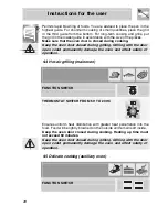
Page 25: ...ls including different types of food fish meat etc without the tastes and smells mingling Air circulation in the oven ensures a uniform distribution of heat Pre heating is not necessary Multiple cooking is possible as long as the cooking temperature of the different foods is the same 9 3 Grill cooking main and auxiliary ovens FUNCTION SWITCH THERMOSTAT SWITCH AT MAXIMUM ...

Page 26: ...ng grilling Grilling with the door open could permanently damage the oven and affect safety of operation 9 4 Hot air grilling main oven FUNCTION SWITCH THERMOSTAT SWITCH FROM 50 TO 200 C Ensures uniform heat distribution with greater heat penetration into the food Food will be lightly browned on the outside and remain soft inside Keep the oven door closed during cooking Heating up time must not ex...

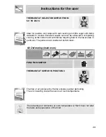
Page 27: ... at the bottom and with dishes requiring heat in the lower area in particular The plate is best inserted at bottom level 9 6 Defrosting main oven FUNCTION SWITCH THERMOSTAT SWITCH IN POSITION 0 The flow of air produced by the fan ensures quicker defrosting The air circulating inside the oven is at room temperature The advantage of defrosting at room temperature is that it does not alter the taste ...

Page 28: ...e bottom Remove handle D and position the spit shaft so that pulley E is guided on the link of frame B Fully insert frame B until the point of the spit shaft enters the spit turning motor housing C on the rear wall of the oven Position pan F on the lowest guide and pour a little water in to avoid smoke forming Make sure that the oven door is closed during cooking It is normal for the thermostat li...

Page 29: ...he surface rinse thoroughly and dry with a soft cloth or deerskin 10 1 2 Food stains or residues Do not use metallic sponges or sharp scrapers they will damage the surface Use normal non abrasive products for steel and a wooden or plastic tool if necessary Rinse thoroughly and dry with a soft cloth or deerskin Do not allow residues of sugary foods such as jam to set inside the oven If left to set ...

Page 30: ...r respective caps taking care that flame spreader holes A correspond to the spark plugs and the thermocouples 10 2 3 Ignition plugs and thermocouples To work well the ignition plugs and thermocouples must always be very clean Check them frequently and clean them with a wet rag if necessary Any dry residue should be removed with a toothpick or a needle 10 3 Cleaning of the oven For best oven upkeep...

Page 31: ...he oven easier to clean and ensure its efficiency over time 10 3 2 Using the self cleaning liners Periodically to prevent food residues and unpleasant smells from accumulating inside the oven the appliance should be operated empty at temperatures of not less than 200 C for a time varying from 30 to 60 minutes in order to allow the self cleaning liners to oxidise the residues present when the oven ...

Page 32: ... 3 Extract the side liners F and G fig 2 4 Remove the back panel A after undoing the threaded ring nut C fig 2 5 Reassemble the panels restoring them to their original position 1 2 10 4 Door glass These should always be kept very clean Use absorbent kitchen paper or in case of hard to remove dirt wash with a wet sponge and ordinary detergent ...

Page 33: ...h as gaskets electric bulbs etc Specific instructions for each intervention of this type appear below Before performing any operations requiring access to powered parts switch off the power supply to the machine 11 1 Replacement of light bulbs Remove cover A by twisting anticlockwise replace bulb B with another similar bulb Refit the cover A Only use oven bulbs T 300 C ...

Page 34: ...ract the pins If the pins are lost two screwdrivers can also be used 11 3 Oven door gaskets The door gaskets can be dismantled for thorough cleaning of the ovens Before removing the gaskets the oven doors must be removed as previously described With the doors removed raise the tabs at the corners as shown in the figure 11 4 Lubrication of gas taps With time it may happen that the gas taps get bloc...

Page 35: ...to be cleaned and re greased this operation must be carried out by an authorised person 12 PROBLEMS AND CAUSES Each of the following cases is caused by an abnormal operation of the appliance and should be dealt with by a authorised persons please contact your local dealer or Service Center in case you detect any of these malfunctioning PROBLEM CAUSE WHAT TO DO The flame is very long with bright ye...

Page 36: ......

Page 37: ......

Page 38: ...914772503 C ...

Reviews: