®
4 Way • 4 and 5 Port
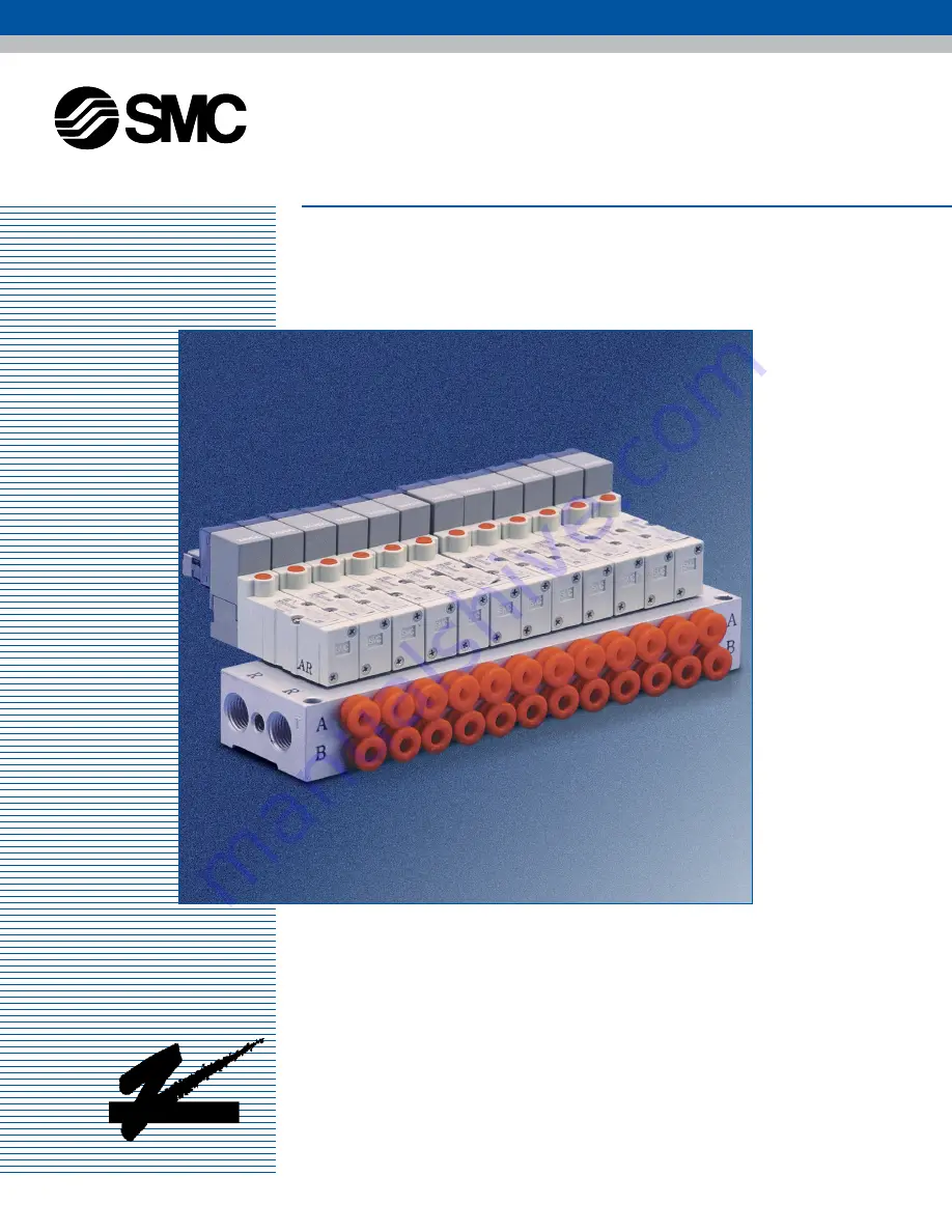
Rubber Seal • Solenoid Pilot Valve
Series SYJ3000
Interchangeable with the NVJ SeriesLow Power Consumption: 0.5WBase Mounted/Body Ported ConfigurationsManifolds with Built-in ‘One-Touch’ Fittings
N244
P R O D U C T S
™
Page 1: ...rt Rubber Seal Solenoid Pilot Valve Series SYJ3000 Interchangeable with the NVJ Series Low Power Consumption 0 5W Base Mounted Body Ported Configurations Manifolds with Built in One Touch Fittings N24...
Page 2: ...Q Q Q Q Q Q Q Q Q Q Q Q Q Q Q Q Q Q Q Q Q Q Q Q Q Q Q Q Q...
Page 3: ...onal Options Air Pilot Type 18 19 Power Conserving Type 20 Drawings Valve 22 28 Manifold 29 34 Operations Guide System Design 36 Installation 37 Maintenance 38 Manual Override 39 Surge Suppressor 40 W...
Page 4: ...ings are realized through the use of a smaller power supply and the elimination of relay cards Compact Design The SYJ produces a high flow rate Cv0 1 while maintaining a slim profile 10mm width Refine...
Page 5: ...Options such as built in one touch fittings and flat ribbon cable connectors simplify installation and reduce setup time Common Exhaust Valves can be ordered with a common exhaust port for the pilot...
Page 6: ...t R Port A B Port P Port R1 R2 Port A B Port P Port R Port P Port R Port Series Type 32 Type 41 Type 46 Type 32P SYJ3000 Base Mounted Manifolds Preferred Option Program The Preferred Option Program Qu...
Page 7: ...QQ QQQQQQQQ QQQQQQQQ QQQQQQQQ QQQQQQQQ QQQQQQQQ QQQQQQQQ QQQQQQQQ QQQQQQQQ QQQQQQQQ QQQQQQQQ QQQQQQQQ QQQQQQQQ QQQQQQQQ QQQQQQQQ QQQQQQQQ QQQQQQQQ QQQQQQQQ Specifications Series SYJ3000 Specifications...
Page 8: ...se of M5 and mounted on manifold base Note2 Without sub plate Note3 For DC voltages For AC voltages add 1g to the weight of the single solenoid and 2g to the weight of the double solenoid and 3 positi...
Page 9: ...valve is wired to the manifold base A single MIL specification flat cable connects the entire manifold to the power source This greatly reduces installation time Manifold Specifications Type Type 21P...
Page 10: ...10 Q Q Q Q Q Q Q Q Q Q Q Q Q Q Q Q Q Q Q Q Q Q Q Q Q Q Q Q Q...
Page 11: ...Q QQQQQQQQ QQQQQQQQ QQQQQQQQ QQQQQQQQ QQQQQQQQ QQQQQQQQ QQQQQQQQ QQQQQQQQ QQQQQQQQ QQQQQQQQ QQQQQQQQ QQQQQQQQ QQQQQQQQ How To Order Series SYJ3000 Valve 12 Manifold 13 14 Accessories 15 Base Mounted B...
Page 12: ...wire with light surge suppression MO Without H 600mm lead wire LOZ W out lead wire with light surge suppression LO U W out lead wire with light surge suppression for flat cable manifold LO Without 24...
Page 13: ...Valve mounting direction S Single solenoid coil is located on the opposite side of the A B port Single solenoid coil is located on same side as the A B port Valve mounting direction S 02 20 2 stations...
Page 14: ...plate ass y SYJ3000 21 4A With dust cap 5 6 5 6 5 6 5 6 Applicable valve SYJ3 23 LOU M3 SYJ3 23Y LOU M3 Applicable valve SYJ3 33 LOU SYJ3 33Y LOU Type 46 5 Port Base mounted type Applicable blank pla...
Page 15: ...nifold Base 4 Port base mounted type SYJ3 30 3 Applicable manifold base SS5YJ3 20 SS5YJ3 21P 5 Port body ported type SYJ3 20 3 5 Port base mounted type SYJ3 40 3 Blank plate ass y SYJ3000 21 1A Blank...
Page 16: ...Q Q Q Q Q Q Q Q Q Q Q Q Q Q Q Q Q Q Q Q Q Q Q Q Q Q Q Q Q 16...
Page 17: ...QQQQQ QQQQQQQQ QQQQQQQQ QQQQQQQQ QQQQQQQQ QQQQQQQQ QQQQQQQQ QQQQQQQQ QQQQQQQQ QQQQQQQQ QQQQQQQQ Additional Options Series SYJ3000 Additional Options 17 Air Pilot Type 18 19 Power Conserving Type 20 Ai...
Page 18: ...Ambient and fluid temperature F Lubrication Mounting position Impact Vibration resistance m s2 2 Position single 2 Position double 3 Position 2 Position single 2 Position double 3 Position Air 22 100...
Page 19: ...9 14 14 15 10 10 5 2 5 5 5 1 5 1 5 1 5 4 8 2 1 5 4 1 5 1 8 22 3 54 5 16 18 9 33 1 5 2 5 11 13 21 28 5 17 5 1 5 Mounting holes M3 0 5 Pilot port M3 0 5 Pilot port 2 M3 0 5 Pilot port 2 M3 0 5 Pilot por...
Page 20: ...ng the wattage required to hold the valve in an energized state SYJ 3 T Z 5 6 24VDC 12VDC Rated voltage Specify the same as standard How to Order Operating principle The circuit shown below reduces cu...
Page 21: ...QQQ QQQQQQQQ QQQQQQQQ QQQQQQQQ QQQQQQQQ QQQQQQQQ QQQQQQQQ QQQQQQQQ QQQQQQQQ QQQQQQQQ QQQQQQQQ QQQQQQQQ QQQQQQQQ QQQQQQQQ QQQQQQQQ QQQQQQQQ Drawings Series SYJ3000 Valve 22 28 Manifold 29 34 List of Sp...
Page 22: ...ub plate Pilot valve Note Zinc die cast Part No SYJ3000 22 1 2 position single 2 position double 3 position closed center exhaust center pressure center B PR R A B PR R A B PR2 R A 3 position closed c...
Page 23: ...Manual override Non locking Manual override R R P A 2 1 8 Mounting holes for manifold 53 6 GZ 54 6 54 6 33 5 13 2 7 1 8 2 4 11 5 7 54 4 GZ 55 1 56 1 49 5 15 13 5 20 15 7 7 10 11 5 M3 0 5 Piping port...
Page 24: ...2 GZ 79 2 79 2 37 18 5 7 1 1 8 8 2 4 7 G About 300 H About 600 78 8 GZ 80 2 82 2 69 18 5 13 5 20 7 7 10 11 0 5 5 M3 0 5 Piping port 15 6 9 28 34 5 A B B A 37 7 1 1 8 98 6 69 8 2 18 5 18 5 20 13 5 4 2...
Page 25: ...30 5 19 5 18 5 5 3 1 8 8 2 4 7 91 7 GZ 93 1 95 1 40 4 GZ 41 1 42 1 46 5 35 5 20 18 5 13 5 Bracket 7 7 10 11 0 5 5 M3 0 5 Piping port 15 6 9 28 34 5 A B B A Bracket 111 6 50 4 8 2 18 5 18 5 20 13 5 4...
Page 26: ...41 5 48 28 5 5 33 5 10 10 14 14 15 5 M5 0 8 Piping port 17 5 11 2 5 54 4 GZ 55 1 56 1 53 6 GZ 54 6 54 6 33 5 22 4 2 3 2 Mounting holes 5 10 10 10 A A B B B B A A R2 R1 P R2 R1 P 33 5 22 4 2 3 2 Mounti...
Page 27: ...10 10 28 5 M5 0 8 Piping port 17 5 11 2 5 78 8 GZ 80 2 82 2 77 2 GZ 79 2 79 2 14 37 22 2 3 2 Mounting holes 5 10 10 9 A A B B R2 R1 P R2 R1 P B B A A 37 22 2 3 2 Mounting holes 17 5 11 2 5 71 4 14 79...
Page 28: ...17 5 11 2 5 91 7 GZ 93 1 95 1 53 3 GZ 54 5 54 5 36 6 GZ 37 6 37 6 37 4 GZ 38 1 39 1 16 5 33 5 22 3 2 3 2 Mounting holes 5 10 10 9 A A B B R2 R1 P R2 R1 P B B A A 33 5 16 5 22 3 2 3 2 Mounting holes 17...
Page 29: ...51 144 14 161 5 154 5 15 172 165 16 182 5 175 5 17 193 186 18 203 5 196 5 19 214 207 20 224 5 217 5 Stations L1 L2 for AC R P R R P R A B A B A B A B A B 11 10 14 5 2 3 5 Mounting holes G About 300 H...
Page 30: ...are the same as type 31 SS5YJ3 S31 Station M3 for AC R P P R A B A B A B A B A B A A B B 12 7 5 25 7 5 2 3 5 Mounting holes G About 300 H About 600 Lead wire length 43 5 50 31 1 24 5 15 12 3 4 M5 0 8...
Page 31: ...0 5 17 199 191 18 209 5 201 5 19 220 212 20 230 5 222 5 Stations L1 L2 SS5YJ3 32 S32 Station N3T SS5YJ3 32 S32 Station M5T R P P R A B A B A B A B A B A A B B A A B B 17 7 5 31 5 10 10 2 4 5 Mounting...
Page 32: ...S5YJ3 S41 Station M5 N3T for AC R R P A B A B A B A B A B A A B B A A B B 21 5 36 5 10 10 2 4 5 Mounting holes G About 300 H About 600 Lead wire length 48 5 55 36 1 29 5 20 15 5 NPTF P port 2n M5 0 8...
Page 33: ...SS5YJ3 S46 Station M5T N3T for AC P P A B A B A B A B A B A A B B A A B B 19 35 10 10 2 4 5 Mounting holes G About 300 H About 600 Lead wire length 48 5 55 36 1 29 5 20 15 5 2 NPTF P port 2 NPTF P po...
Page 34: ...tor polarity indication Applicable connector 26 pole MIL type Conforms to MIL C 83503 2n M3 0 5 A B port 17 7 5 31 5 10 4 NPTF P R port P R R P B A B A B A B A B A B A A B A B A B A B 29 8 15 5 Pitch...
Page 35: ...o remove component until safety is confirmed 1 Inspection and maintenance of machinery equipment should only be performed after confirmation of safe locked out control positions 2 When equipment is to...
Page 36: ...taminants that may lead to valve malfunction System Design Precautions Energization time The double solenoid valve must be energized for at least 0 05 second to ensure proper operation Leakage Voltage...
Page 37: ...tion Seal tape 2 thread to be left exposed Lubrication The valve has been lubricated for life at manufacture and does not require lubrication in service If a lubricant is used in the system use turbin...
Page 38: ...the system Lock out valve for release of residual pressure is recommended When the machine is to be restarted check first that actuators are in their proper start up positions Low frequency operation...
Page 39: ...ble for applications where exhausting the pilot valve to atmosphere would be detrimental to the surrounding working enviroment For use in extremely dirty environments where there is the possibility th...
Page 40: ...Wrong polarity will cause damage Solenoids whose lead wires have been pre wired are positive side red and negative side black Z N R Coil Coil Coil Coil Indicator light and surge voltage suppressor Z...
Page 41: ...1 2 3 26 from the triangle mark side on the flat cable of connector For more than 10 stations both poles of the common should be wired For single solenoid connect to the solenoid B side The maximum nu...
Page 42: ...t with plug VJ3000 33 1 Applicable solenoid valve Type SYJ312 Type SYJ312M Type SYJ322 Type SYJ322M Type SS5YJ3 31 S31 SS5YJ3 32 S32 SS5YJ3 46 S46 SS5YJ3 32P The 3 way valve can be used on the 4 way m...